


4
Introduction:
Overview and Illustrations
The DSP-30 and Signal Manager software combine easy-to-
use, customizable, two-channel DSP with simple operating-
mode selection that requires only two buttons to operate. It
can be used with all amplifiers and is housed in a 1-RU , 19-inch
rack-mount steel chassis. Sampling frequency is 48 kHz. with
24-bit resolution. Dynamic range is greater than 93dB. It is
absolutely rugged and dependable in the spirit of all QSC
professional audio products and fully suited for the rigors of
touring use.
Processing capabilities of the DSP-30 include compressors,
limiters, delays, parametric EQ, high/low pass filters, high/low
shelf filters, test signal generators (sine-wave, pink- and
white-noise), splitters/mixers, polarity reversal, gain/attenu-
ation, and metering. A feature called “Predictive Delay” en-
ables the DSP-30’s compressors and limiters to produce less
signal distortion than their analog counterparts, especially for
fast attack times. Predictive delay adds time delay to the signal
path and must be accounted for to maintain proper time
allignment. Using the Signal Manager software, predictive
delay may be turned on or off; when on, it will provide time
delay information to the operator.
The DSP-30 provides powerful signal processing while keep-
ing operation as simple. Preset operating modes are user-
selectable by scrolling through the list of numbered Presets on
the front panel display and selecting. The DSP-30 will mute,
Overview
Front Panel
Power switch
Signal indicator LED’s
Multi-segment LED numeric display
Browse button
Accept button
RS-232 connector
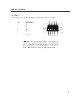
Rear Panel
reconfigure, and unmute in a fraction of a second, providing
smooth transitions free of thumps, clicks and other undesir-
able audio artifacts. The contact closure input feature allows
for instantaneous gain changing and other programmable
uses.
Use the QSC Signal Manager software to create the preset
configurations. Please refer to page 11 for computer system
requirements and software installation guidelines. For in-
structions for creating a simple signal processing chain, refer
to the software help file. QSC’s Signal Manager software
provides an easy-to-use graphical user interface where DSP
“objects” are placed onto a workspace and interconnects are
drawn. This interface allows almost infinite configuration
possibilities.
Signal Manager transfers the preset data to the DSP-30
through a serial data cable. The cable connects between the
computer’s COM port and the DSP-30’s RS-232 port. Once the
presets have been loaded, connection to the computer is no
longer required. This feature allows essentially tamper-proof
DSP setup. Stored presets can be recalled using the front
panel Select button. Modification of stored presets, or the
creation of new presets can be implemented by connecting a
computer and loading the new presets into the DSP.
The DSP-30 will provide many years of reliable, professional
quality signal processing. From all of us at QSC Audio Prod-
ucts, “Thank you.”
Input Connectors
Output Connectors
AC Power Connector
Power ‘on’ indicator LED
Содержание DSP-30
Страница 5: ...5 Introduction Illustrations and Dimensions Dimensions...
Страница 21: ...21 Use Application Example TRI AMPED PA CABINETS WITH SUBWOOFER Sample Application Diagram...
Страница 26: ...26 Notes...
Страница 27: ...27 Notes...