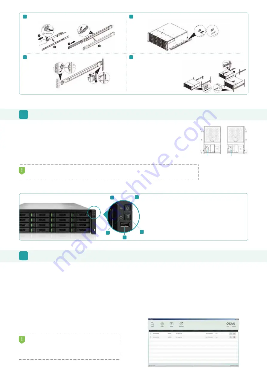
4. See the diagram below to determine the meaning of the lights and indicators on the front of the system.
TIP:
Please wait for the controller status LED to turn green on the rear of the chassis before attempting to discover or manage the storage system.
It may take a few minutes to boot the XCubeSAN system.
5
POWER ON THE STORAGE SYSTEM
Connect the Power Cables
1. Connect power cables from each power supply module to a power source.
2. Make sure to secure the power cables the power supply modules so they can not be pulled out accidentally.
Power on the System Components
1. Power on any network switches, routers, or other standalone components.
2. Power on any expansion enclosures that might be a part of the system.
3. Power on the XCubeSAN system by pressing the power button on the front of the system.
Power Cord
Conncctor (left)
Power Cord
Conncctor(right)
Pull the inner rail out and slide the intermediate member back.
Install the inner rail onto the chassis.
Insert the chassis to complete the installation.
Rear Bracket
Front Bracket
Note : Please repeat the installation steps for the other side.
6
DISCOVER AND SETUP THE SYSTEM
Discover the System
The default setting for the management IP address is DHCP. We provide the XFinder Java utility to search for QSAN products on the network and
aid quick access to the login page of the SANOS web interface.
XFinder Utility
To download XFinder, please visit :
https://www.qsan.com/download_center
XFinder is a Java based program. To execute this program, JRE (Java Runtime Environment) is required. You can visit the following website to
download and install JRE :
http://www.java.com/download/
After JRE is installed, run the XFinder.jar program. The SAN storage system in your network will be detected and listed in the table.
Select the system you are looking for. Double clicking the
selected entry will automatically bring up the browser and
display the login page.
TIP:
If the LAN doesn’t have a DHCP server, the management port will be
assigned a fix IP address: 169.254.1.234/16. So you can configure the IP
address of your management computer to the same subnet domain of the
storage system, e.g.: 169.254.1.1/16. Then open a browser and enter
http://169.254.1.234 to go into the login page.
1
2
4
Install the outer rail / bracket assembly to the frame.
3
Step 1. Pull the middle rail fully extended in locked position.
Step 2. Ensure ball bearing retainer is located at the front of the middle rail.
Step 3. Insert chassis into middle-outer rail.
Step 4. When hit the stop, pull / push release tab to unlock and retract chassis into rack.
Step 5. Use M5x20 screws to fasten the chassis ear.
1. System Power Button / LED
4. System Status LED
2. UID (Unique ldentifier) Button / LED
5. USB Port
3. System Access LED
1
2
3
4
5


