XCubeFAS Series
Hardware Manual
Quick Maintenance
© 2021 QSAN Technology, Inc. All rights reserved.
www.qsan.com
Official
Document
52
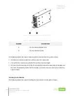
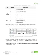
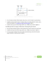
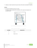
Table 4-9 Components of XF2026D Cache-to-Flash Modules
ITEM
NUMBER
DESCRIPTION
Flash
Module
1
Flash Module Release Tab
2
Flash Module Attention Button
3
Flash Module Handle
4
Flash Module Status LED
5
Flash Module Power LED
Power
Module
6
Power Module Release Tab
7
Power Module Handle
▪
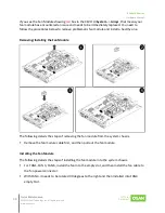
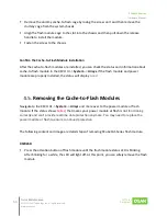
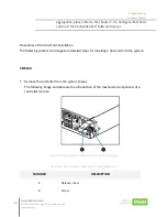
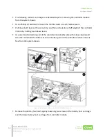
Remove the dummy cache-to-flash cage by losing the screw on it and then remove the
dummy cage from the system chassis. Follow the same procedure for both sides.
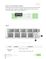
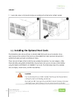
Figure 4-14 The Dummy Cage Screw Location of XF2026D Cache-to-Flash Module
▪
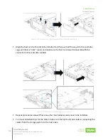
Align the flash module cage to the slot and then push it all the way into the system chassis
until hear a “click” sound (
for 2U chassis release tabs of both flash and power modules are
facing upward while installing into the system).
▪
Align the power module cage to the slot and then push it all the way into the system chassis
until hear a “click” sound.

