XCubeFAS 2026
Hardware Manual
System Components Overview
© 2021 QSAN Technology, Inc. All rights reserved.
www.qsan.com
Official
Document
19
BIOS and CPU to quickly backup memory RAM data to the flash module. In order to quickly
move data from memory RAM to flash module, M.2 PCI‐Express interface flash module is
selected for better performance and less power consumption. In Cache‐to‐Flash recovery phase,
BIOS will check C2F flag status. If C2F flag is ON, I/O cache data will be recovered from the M.2
flash module and then continue normal booting. If C2F flag is OFF, the normal booting process
continues. Compared with traditional BBM solution of 72 hours standard, Cache-to-Flash
technology is more efficient, less risky and consumes less power.
2.5.2.
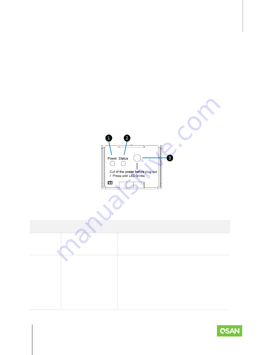
Cache-to-Flash Module LEDs and Button
Please refer to the following for the definition of LED and button behavior.
Figure 2-15 Flash Module LEDs and Button
Table 2-13 Descriptions of Flash Module LEDs and Button
NUMBER
DESCRIPTION
DEFINITION
1
Power LED
Solid
Green
: Power is good at flash module.
Off: There is no power at flash module.
2
Status LED
Solid
Blue
: The status of flash module is
good.
Blinking
Blue
and
Amber
Interlaced: Installing
or removing the flash module.
Solid
Amber
: The flash module is failed or
wrong PCIe connection speed.


