4
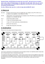
Fit the tall 10-way (5 x 2) pin header connector, pictured to the right, to the Ultimate3
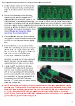
PCB. The board photo (above right) shows the old (pre 6-Feb-2014 shipped kits)
board interconnect method, using the standard-height header. Insert the tall header
(right), with the short pins into the PCB, and the tall pins sticking up next to the relay.
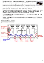
Fit the 10-way (5 x 2) socket to the bottom side of the relay kit PCB (tracks side, not the components
side). This will mate with the long pins of the tall header fitted to the U3 PCB.
The easiest way to ensure that the plug and socket are perfectly aligned is to assemble the U3 and the
relay PCB in their final configuration, bolting the PCB's together using the 25-mm hex spacers, but
WITHOUT soldering yet. This will ensure correct orientation of all the connectors.
It will still help to temporarily remove the LCD from the U3, so that you can access the U3-side header
with your soldering iron.
When the two boards are bolted together and the connectors perfectly aligned, you can solder the 10-
way connectors.
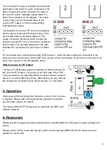
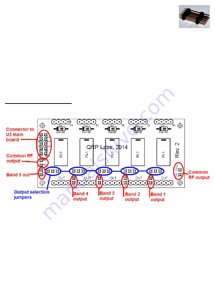
Connection of wire jumpers
Please refer to the diagram below.


