2
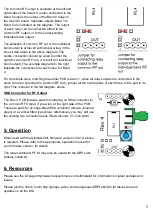
Note that the Rev 2/3/4 PCB allows the output side of each LPF / relay-switch to be connected
either to the common RF Output signal, or to individual connection pads. In this way, you can use
either a single antenna, or connect different antennas for each band. The choice is arranged by
wire jumpers, described below.
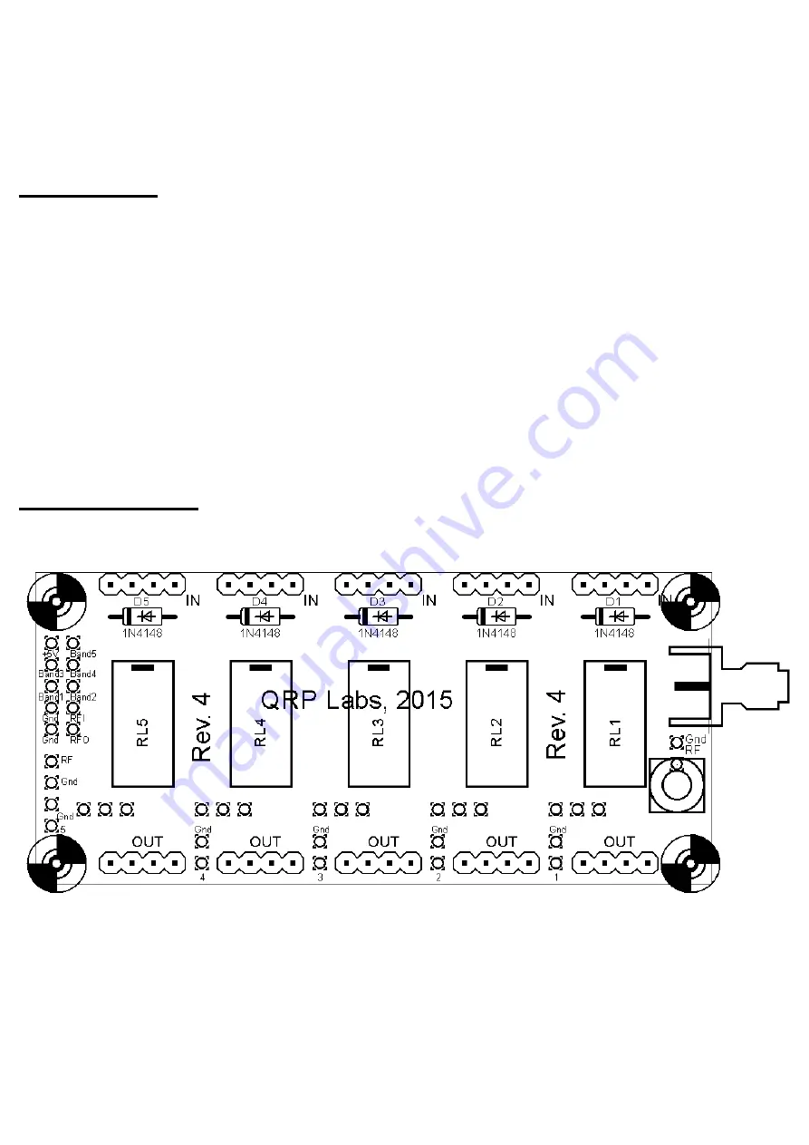
The Rev 4 PCB provides space for a vertical or edge-mounted SMA RF socket.
3. Parts List
RL1-RL5
Panasonic TX2-5V relays. Six are supplied (five are installed on the LPF kit PCB, one is
provided for the installation on the Ultimate3 kit PCB)
D1-D5
1N4148 diode. Six are supplied (five are installed on the LPF kit PCB, one is provided for the
installation on the Ultimate3 kit PCB)
10 of
4-way female header sockets
1 of
10-way (2 x 5) female header socket
1 of
10-way (2 x 5) male header plug, extended (tall) size
4 of
25mm nylon hex spacers
1 of
Printed circuit board, 80 x 37mm size
4. Construction
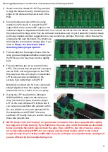
Please refer to the parts placement diagram below.
The order of construction is not important but a good principle to follow is to install the smaller components
first, so that the larger ones do not prevent easy access.
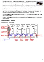
The following photographs show PCB Rev 1; later revisions are the same but have additional jumper pads
to facilitate the use of multiple antennas if required (described below). The Rev 2 PCB also has silk-screen
text labels “IN” and “OUT” to ensure that you plug in the low pass filter modules with the correct
orientation.


