background image

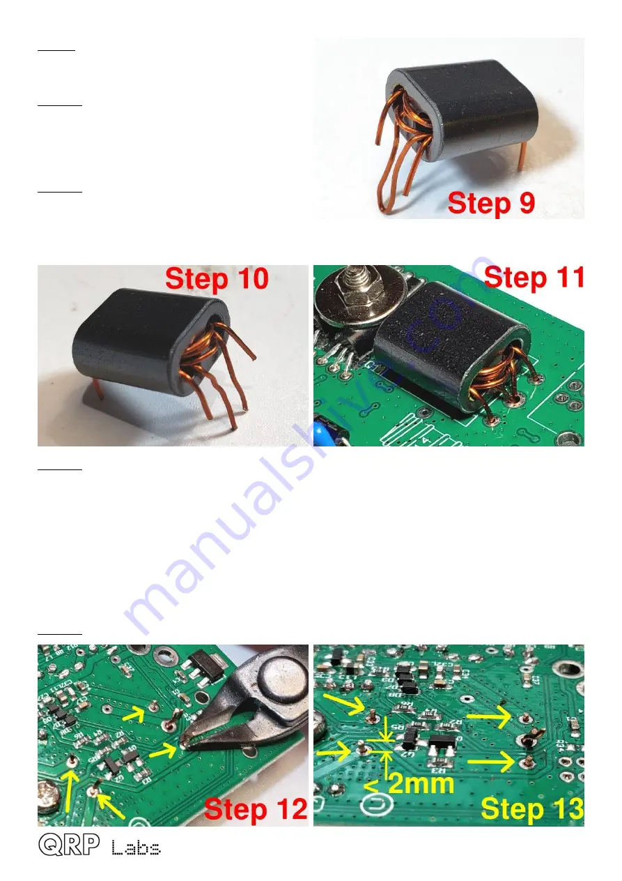
Step 9

: Bend all the wires to point downward in

the position they will need to be, to fit through the
holes in the PCB. 

Step 10

: Now cut the center-tap loop; hopefully,

as mine are in this photograph, these two wires
formed by cutting the loop are LONGER than the
two ends of the 3-turn secondary, so that you
cannot mix anything up. 

Step 11

: Insert the wires into the holes on the

PCB. The two wires (of the cut loop) that belong
to the center-tap of the 3-turn primary, which are
the longer wires, are inserted into the middle hole
on the right-hand side; this hole is larger than the others and is big enough for both wires to fit in. 

Step 12

: Now we need to get the enamel off the wire. Usually on thinner wire, I hold the soldering 

iron to the wire until the enamel burns off. But that doesn’t work so well on thicker wire such as 
this. So my technique here is to scrape the enamel off, at least partially, using wire cutters. The 
correct pressure needs to be applied to the wire cutters, so as NOT to actually cut the wire. I hold 
the wire cutter as close to the PCB as possible, then gently but firmly pull the cutter away from the 
PCB, scratching off the enamel. Turn the cutter to a different angle and scrape again, 2 or 3 times.
It is not necessary to remove ALL the enamel, if you get a few good scrapes on, enough enamel 
will be removed that the soldering iron heat will burn off the rest of the enamel and a good joint will
be achieved. Do this for the 4 winding ends first, leave the two center-tap for later, to make it 
easier. 

Step 13

: Cut each of the four wire-endings, leaving about 2mm or less, sticking up from the PCB. 

QDX assembly Rev 1.00

19

Содержание QDX

Страница 1: ...QDX QDX QRP Labs Digital Xcvr transceiver Assembly design and operating manual QDX assembly Rev 1 00 1...

Страница 2: ...zed local oscillator 47 4 4 Solid state transmit receive switch 50 4 5 Switched receiver band pass filter 51 4 6 Double balanced Quadrature Sampling Detector 52 4 7 Low noise pre amplifiers 53 4 8 Dig...

Страница 3: ...n suite of configuration and analysis tools Lifetime free firmware upgrades with QRP Labs Firmware Update QFU bootloader for easy firmware update on any OS with no extra software or drivers or program...

Страница 4: ...manual Remember this when you come to the assembly step for preparing and installing the output transformer T1 The primary is still 3 turns with a tap half way at 1 5 turns The secondary no tap will n...

Страница 5: ...components so it is much better to get them correctly installed the first time In the event of a mistake it is always best to detect and correct any errors as early as possible immediately after sold...

Страница 6: ...QDX assembly Rev 1 00 6...

Страница 7: ...QDX assembly Rev 1 00 7...

Страница 8: ...QDX assembly Rev 1 00 8...

Страница 9: ...10 11 12 13 14 17 18 26 27 29 3 100K SMD R15 16 19 3 470K SMD R7 8 9 Capacitors 50V Multi layer Ceramic capacitors Qty Value Description Component numbers 1 22pF Label 220 C29 1 30pF Label 300 C31 2 4...

Страница 10: ...SMD BC857 PNP T3 1 SMD BC817 NPN T4 1 SMD Red LED DIAG 1 3mm Red LED PANEL Inductors Qty Description Component numbers 6 SMD 47uH L11 13 15 16 17 18 4 47uH radial inductor L1 5 7 9 replace SMD induct...

Страница 11: ...33 mm diameter wire AWG 28 1 50 cm 0 60 mm diameter wire AWG 22 1 M3 12mm Steel 12mm long M3 screw 1 M3 Steel M3 nut 1 M3 12mm Steel 12mm diameter M3 washer Enclosure OPTIONAL Qty Value Description 2...

Страница 12: ...2 3 Inventory parts QDX assembly Rev 1 00 12...

Страница 13: ...r body which is coloured yellow The actual value e g 220pF is written in red text next to the capacitor Note that the leads of the 56pF capacitor 56J need to be bent to fit the 2 5mm holes Qty Value D...

Страница 14: ...cally important The diodes have a black body and a white stripe The white stripe end must be aligned with the white stripe on the image on the PCB silkscreen In the diagram below all the white strip e...

Страница 15: ...nsistors in the positions shown with their flat faces flush against the PCB Use the 12mm M3 bolt washer and nut to firmly press the transistor faces against the PCB as shown Refer to the diagram and p...

Страница 16: ...leads soldered in step 3 2 Solder them in the positions shown soldering on the bottom side of the board Photo below left Next slide the TCXO module onto the wires and lower it to sit flat on the main...

Страница 17: ...up back at the end where it started Assembly of this transformer is best done in steps as follows Please read all the steps before commencing the assembly Step 1 Carefully unwrap the thick 0 6mm AWG 2...

Страница 18: ...the wire coming out of the bottom left hole as shown cut it to about 1cm protrusion Step 6 Squeeze together the center tap to try to avoid subsequent confusion Step 7 Start the 3 turn secondary windi...

Страница 19: ...ring iron to the wire until the enamel burns off But that doesn t work so well on thicker wire such as this So my technique here is to scrape the enamel off at least partially using wire cutters The c...

Страница 20: ...oint for maybe 15 seconds to really be sure of a good joint and burning away any remaining enamel Step 16 Check that none of the wires protrude more than 2mm from the surface of the PCB since if you a...

Отзывы: