background image

DURAWATT

® 

ELECTRIC WATER HEATER 


PV500-6   09/07


13


SUPERTANK

 BOLTED HEAD REMOVAL 

 
SUPERTANK

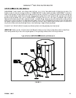
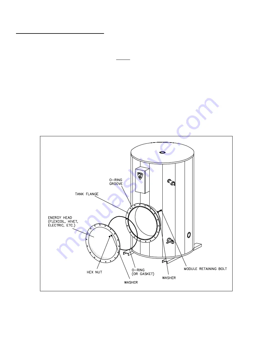
 water heaters and storage tanks will have one or more removable heads or bolted tank sections. The 

heads are used to mount an energy module (i.e. TURBOPOWER

®


module, electric elements, QUICKDRAW

®

 or steam or 

water heat exchanger heating elements) or bolted head for access to the tank. If a head or module is removed during the 
course of maintenance, replace the O-ring and all special high quality 9/16”-12 NC, grade 8 bolts, washers and nuts with 
identical parts available from your PVI representative or directly from PVI. Do not reuse or substitute these special 
fasteners with similar grade 8 bolts, washers and nuts.  Install the flange bolts and nuts with a flat washer under each bolt 
head and nut. First, snug them in an alternating star pattern. Then, using a calibrated torque wrench, and in an alternating 
star pattern, tighten the bolts in 2 increments: 95 ft lbs and 145 ft lbs. Use a small amount of silicone RTV to hold the o-
ring in place while positioning the flanged head or heat exchanger. Apply adhesive sparingly! 


Contact PVI at 1-800-433-5654 for replacement Fastener Kits and O-Ring Replacement Instructions.   


IMPORTANT

: Mark one hole on head and on tank flange for reference when removing head. Be certain to align these 

holes during reassembly to insure the original gasket or O-ring mating surfaces will be correctly positioned. 


Typical Vertical SUPERTANK

 Bolted Head Attachment 


FIGURE 13 


Содержание 500-6

Страница 1: ...t perform installation and service WARNING Do not use this appliance if any part has been under water Immediately call a qualified service technician to inspect the unit and to replace any part of the control system and any other items affecting safe appliance operation Failure to follow these instructions can cause property damage personal injury or loss of life TO THE INSTALLER After installatio...

Страница 2: ...DURAWATT ELECTRIC WATER HEATER PV500 6 09 07 2 TYPICAL CONSTRUCTION FIGURE 1 Without 23 Diameter Tank Access FIGURE 2 With 23 Diameter Tank Access ...

Страница 3: ...THE PHYSICALLY HANDICAPPED HOSPITALS AND NURSING HOMES ELDER CARE FACILITIES AND REST HOMES ORPHANAGES AND CHILD CARE FACILITIES OTHER INSTALLATIONS WHERE RESPONSE TO CONTACT WITH HOT WATER MAY BE SLOWER OR WHERE THE DANGER OF HOT WATER CONTACT IS GREATER Thermostatically controlled mixing valves must be used in the design of the potable hot water system Potable hot water should be tempered to no ...

Страница 4: ... 3 Locate the foundation on a pitched floor near a suitable drain or make other provisions to prevent contact to areas of the building subject to water damage should the boiler or a water connection leak The drain must be sufficient to contain water in excess of 210 F INSTALLATION WARNING Use industry standard safe rigging methods when attempting to lift or move this product Failure to follow thes...

Страница 5: ...MPORTANT Check all wiring connections in heater and element enclosure to assure tightness prior to energizing NOTE Use only copper wire of proper sizing for incoming service Damage resulting from use of aluminum wiring is excluded from coverage under the warranty of this unit ELECTRONIC LOW WATER CUTOFF The device consists of a probe in the tank that acts as a switch closed when submerged in water...

Страница 6: ...e elements have 3 terminals 1 phase elements have 6 terminals FIGURE 3 2 Check all electrical connections for tightness before turning the unit on 3 Energize manual disconnect switch Check for proper voltage with voltmeter on power circuit Voltage should not vary more than 5 from voltage shown on data plate If voltage exceeds these limits immediately turn off main disconnect and contact utility co...

Страница 7: ...proper performance MAINTENANCE A preventative maintenance program is required to ensure a long trouble free life of the water heater Maintenance Schedule COMPONENT OPERATION INTERVAL REQUIRED Tank Sediment Removal Every 3 Months Flushing Relief Valve Inspect Every 6 Months Test Electrical Connections Inspect Monthly Inspect for wire discoloration Electric Elements Check Every 6 Months Amp Draw Ele...

Страница 8: ...ief valve mounting location Low Water Cut Off The standard low water control is electronic Inspection should be made of the electrode on water heaters equipped with electronic low water devices Electrical Connections Check all electrical connections approximately one to two weeks after initial start up to assure tightness Heating and cooling from operation can loosen connections Visually inspect w...

Страница 9: ...of the scale buildup is also determined by the watt density of the element It is good maintenance practice to remove and clean 80 W in 18kW density elements on a monthly basis The interval between removal and cleaning can usually be extended to six months when 40 W in 9kW density elements are installed Most installations where 20 W in 4 1 2kW density elements are used require only annual cleaning ...

Страница 10: ... READING MAY VARY FROM ZERO DIRECT SHORT TO SEVERAL HUNDRED OHMS PARTIAL SHORT IN ANY CASE WHERE THE OHM READING IS NOT INFINITY THE ELEMENT SHOULD BE REPLACED B C 26 39 39 C A 26 39 18 240 A B 7 20 B C 7 10 10 C A 7 10 18 208 A B 5 15 B C 5 7 5 7 5 C A 5 7 5 9 480 A B 51 153 B C 51 76 5 76 5 C A 51 76 5 9 240 A B 13 39 B C 13 19 5 19 5 C A 13 19 5 9 208 A B 10 30 B C 10 15 15 C A 10 15 4 5 480 A ...

Страница 11: ...DURAWATT ELECTRIC WATER HEATER PV500 6 09 07 11 FIGURE 7 FIGURE 6 TYPICAL WIRE TERMINATIONS FIGURE 8 TYPICAL SINGLE PHASE WIRING TYPICAL THREE PHASE WIRING FIGURE 10 FIGURE 9 ...

Страница 12: ...efore the 40W in 2 is rated for 14 kW instead of 9 kW KW VOLTAGE 3 Ø AMPS PER ELEMENT 1 Ø AMPS PER ELEMENT AMPS PER LEG AMPS TOTAL AMPS PER LEG AMPS TOTAL 14 kW 600V 13 1 2 13 1 2 7 kW 600V 7 7 18 kW 480V 22 22 9 kW 480V 11 11 4 5 kW 480V 5 1 2 5 1 2 18 kW 240V 44 44 25 75 9 kW 240V 22 22 13 38 4 5 kW 240V 11 11 6 18 18 kW 208V 50 50 29 87 9 kW 208V 25 25 15 44 4 5 kW 208V 12 1 2 12 1 2 7 22 TABLE...

Страница 13: ...ecial fasteners with similar grade 8 bolts washers and nuts Install the flange bolts and nuts with a flat washer under each bolt head and nut First snug them in an alternating star pattern Then using a calibrated torque wrench and in an alternating star pattern tighten the bolts in 2 increments 95 ft lbs and 145 ft lbs Use a small amount of silicone RTV to hold the o ring in place while positionin...

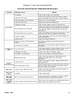
Страница 14: ...put Consult local PVI representative Hot water lines not insulated Add insulation it will protect against heat loss and save on cost of operation Power fuse s blown Check fuses for continuity Replace if blown If blown determine cause of break before replacing with same type fuse Contractor s not closing Check coil for continuity If defective replace Thermostat s not correctly set Check to assure p...

Отзывы: