


PCP Series Manual
Revision A
/
September 2020
Page 40 of 46
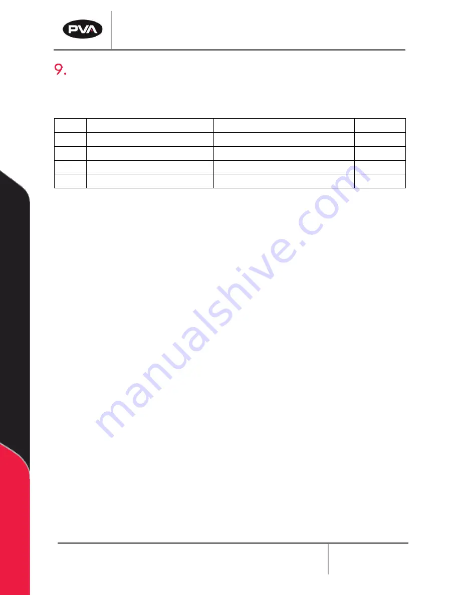
Spare Parts
A spare parts kit is available to prevent machine downtime.
Part Number:
612-10811-1
ITEM
PART NUMBER
DESCRIPTION
QTY
1
12830
O-RING, SS5, PCP050
8
2
12831
O-RING, AN016, PCP050
2
3
12836
O-RING, FKM, AS013, PDP050
2
4
12837
O-RING, FKM, P9, PDP050
2
Figure 49: Spare Parts Kit


