Nixie Clock Kit ' Maestro’
ISSUE 5 (01 June 2018)
www.pvelectronics.co.uk
- 9 -
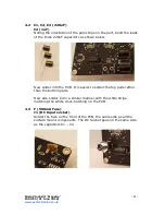
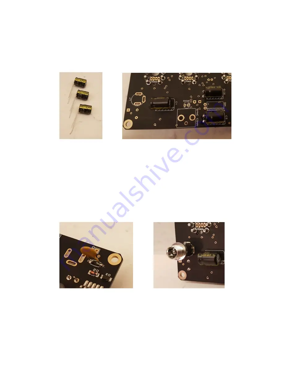
4.2 C1, C2, C3 (220uF)
C4 (1uF)
Noting the orientation of the pale stripe on the part, bend the leads
of the three 220uF capacitors as shown below.
Now solder into the PCB. It is easier to solder the top pads rather
than the bottom pads.
Now also solder C4 in a similar manner,with the white stripe
matching the white cross-hatching on the PCB.
4.3 F (500mA Fuse)
J1 (DC Input socket)
Solder the fuse on the front of the PCB, the same side as all the
surface mount components. The DC Socket goes on the same side
as the capacitors C1 – C4.


