Nixie Clock Kit ' Maestro’
ISSUE 5 (01 June 2018)
www.pvelectronics.co.uk
- 12 -
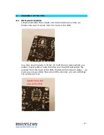
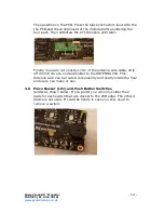
Then position on the PCB. Press the black connectors level with the
the PCB,and check alignment of the module before soldering the
four pads. Then withdraw the CY18 module until later.
Finally, measure out exactly 17cm of the antenna wire cable, strip
off 2mm from one end and solder to the ANTENNA Pad. This
Antenna wire can be routed conveniently and neatly inside the final
enclosure you make or buy.
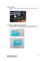
4.9 Piezo Buzzer (LS1) and Push Button Switches
Solder as shown below. If you prefer you can only solder the 2
pads for each switch that are closest to the PCB edge. The other 2
pads are not used. It could be handy in case you ever need to
remove a switch.


