Nixie Clock Kit ' Maestro’
ISSUE 5 (01 June 2018)
www.pvelectronics.co.uk
- 10 -
4.4 Tube Test
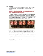
Now comes a very exciting part of the assembly – the first tube
test. Take your six Nixie Tubes and carefully insert into the
sockets.
Take care, as high voltage will now be generated. Do not
touch the PCB when it is powered.
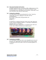
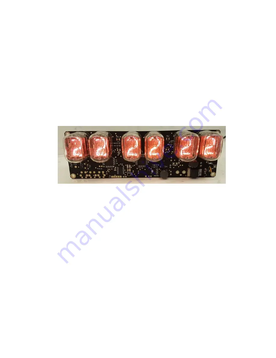
Now power up. After a short delay, the tubes should light and all
start counting from zero to 9 and repeat. Please note this is a
count up, not a count down. If you contact us with a support issue
at this stage, please be clear. If you refer to a count down, it will
be very confusing and slow down your support query!
If you do not get this count up, or have missing or overlapping
digits, stop and check your work. Try swapping tubes around to
see if the problem is with the tube, or the location. Please make
these basic tests before contacting us for help and have the results
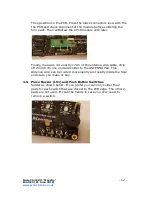
to hand. If no tubes light, check the 5V and HV test points with
your multimeter, with the black probe on the GND test point. The
5V test point should measure 5.3V to 5.9V and the HV test point
165V to 178V.
Once the tube test is complete, remove the tubes until the PCB is
fully assembled.


