Puro PURO-35T Скачать руководство пользователя страница 10

10

B.  Feed Water Saddle Valve Installation 

  Decide on location. Do NOT connect to a 

hot water feed line. If you are not sure of the 

supply, run the hot water and feel the supply 

piping. Water over 100°F may cause permanent 

damage to the R.O. Membrane. (Refer to Fig. 3) 
1.  Shut off the water supply and drain the line.
2a. To install on (soft) Copper Tubing supply  

line:
•Turn the Handle of the Feed Water Saddle 

Valve counter clockwise (outward) until the 

lance does not protrude from the gasket. It 

may have to be pushed in. 

•Assemble the Feed Water Saddle Valve on 

the tubing.

– for 

3

/

8

" OD tubing use the back plate side 

with the small groove to prevent distortion 

of the tubing. 

– for larger tubing (up to 

5

/

8

" OD) use the 

large groove of the back plate. 

•Assemble and tighten the brass screw. 
•To pierce the tubing, turn the Valve Handle 

fully clockwise (inward). A small amount of 

water may escape from the outlet until it is 

fully pierced. 

•When you feel the Valve Handle firmly 

seated in the clockwise direction, the 

copper tube is pierced and the valve is 

closed.

2b. To install on (hard) steel or brass tubing 

supply line. 
•The supply line should now be drained. Use 

a battery powered or properly grounded drill 

to avoid shock hazard. 

•Drill a 

3

/

16

" hole in the supply line; (do not 

drill through the opposite wall). 

•Turn the handle to expose the lance no 

more than 

3

/

16

" beyond the rubber gasket. 

•Place the body of the valve over the hole so 

that the lance fits into the hole. 

•Assemble and tighten the brass screw. 
•Turn the Valve Handle clockwise (inward) 

until firmly seated. The valve is closed. 

3.  With the Feed Water Saddle Valve closed, 

open the sink faucet and the water supply 

and allow the water to run for a few minutes 

to flush any debris caused by the installation. 

•Close the faucet and check the Feed Water 

Saddle Valve for leaks.

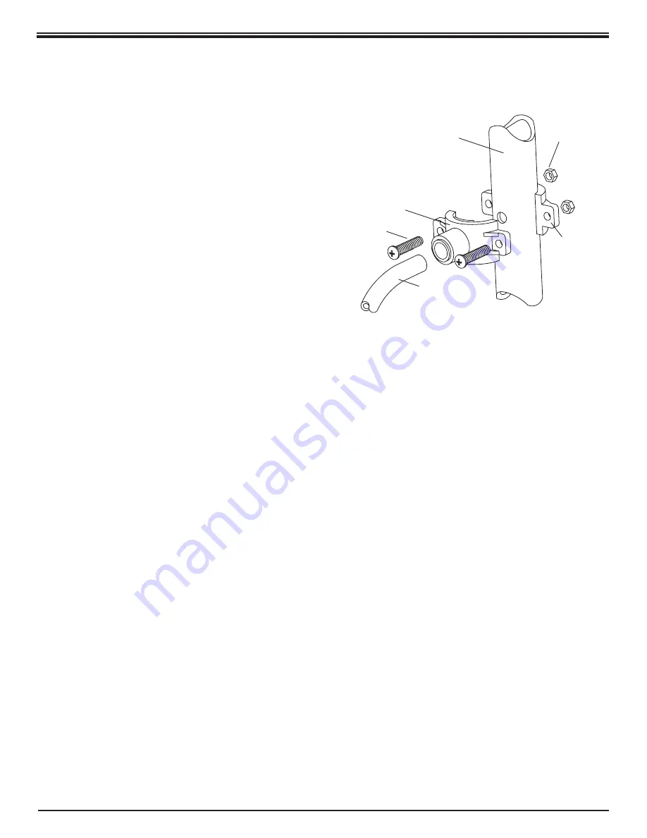
3/8" DRAIN CLAMP ASSEMBLY

Drain Clamp

Front Plate

Drain Pipe

1/4" Nut

1/4" Screw

Drain Clamp

Back Plate

Black Drain Tubing

Figure 4 

C.  Drain Clamp Installation


  Choose the drain outlet location per Sec. III, C.5. 
  The following are instructions for discharging 

into the sink drain pipe. (Refer to Fig. 1.) 
1.  Position the Drain Clamp on the sink drain 

pipe above the drain trap. Allow room for 

drilling. Tighten securely. 

2.  Use a battery powered or properly grounded 

drill. Using the Clamp port as a drill guide,  

drill a 

7

/

32

" hole through the wall of the drain 

pipe. Do NOT penetrate the opposite side of 

the pipe. 

3.  Locate the 

3

/

8

" Black Drain Tubing connected 

to the Dispensing Faucet. Route to the tubing 

to the Drain Clamp and trim to length. 


NOTE:

 When cutting the polytubing make  

clean, square cuts, failing to do so could 

result in poor connections and possible 

leaks. 


CAUTION:

 The lowest point of the line 

should be the point of connection to the Drain 

Clamp. There should be no sag in the line as 

this may cause excessive noise as the reject 

water is flowing to drain.
•Refer to Fig. 4. Insert the tubing into the 

Drain Clamp. Make sure the tubing is 

pressed all the way in to create a pressure 

tight connection.

Содержание PURO-35T

Страница 1: ...Tested and Certified by NSF International against NSF ANSI Standard 58 for the reduction of the claims specified on the Performance Data Sheet MODEL PURO 35T INSTALLATION OPERATION SERVICE MANUAL ...

Страница 2: ...ertains to people with HIV AIDS patients receiving treatment for cancer recipients of organ or bone marrow transplants transplant patients taking immunosuppressive drugs and persons who have congenital immunodeficiencies The EPA has stated that they do not know the significance of drinking water compared to other possible sources of Cryptosporidium to determine how most people become infected The ...

Страница 3: ...duct water tank is full and closes the feed water supply to prevent excess reject water from going to drain when the unit is not producing water WATER QUALITY MONITOR The Water Quality Monitor has been integrated into the faucet base for instant monitoring at the touch of a button The monitor compares the level of the Total Dissolved Solids in the incoming feed water versus the product water and c...

Страница 4: ...t is available to the user as reverse osmosis treated water when the system is operated without a storage tank or when the storage tank is bypassed Efficiency rating means the percentage of the influent water to the system that is available to the user as reverse osmosis treated water under operating conditions that approximate typical daily usage This reverse osmosis system contains a replaceable...

Страница 5: ...e screws and nuts for mounting the manifold or concrete anchors for hanging on basement wall Additional tubing or tube connectors Plastic wire ties for organizing tubing TYPICAL PURO 35T UNDER SINK INSTALLATION DIAGRAM Figure 1 Dispensing Faucet with Air gap drain clamp drain 3 8 Black PRODUCT 3 8 Blue drain 1 4 Black INLET 1 4 Red TANK 3 8 Yellow DRINKING WATER HOLDING TANK HOLDING TANK SHUTOFF V...

Страница 6: ... POST FILTER HOUSING sediment carbon PREFILTER HOUSING BASEMENT FLOOR please note if air gap in faucet is not used in basement installations a proper air gap must be created please check with local plumbing codes see example above FLOOR FEED water saddle valve cold water line only INLET 1 4 Red DRAIN 1 4 Black 1 air gap required POLYTUBE TEE IN LINE ACTIVATED CARBON POST FILTER 1 4 Yellow Water qu...

Страница 7: ...en area beneath the faucet under the sink for attaching product and drain tubing are considerations A 2 diameter flat surface is required above and below the installation site The thickness of the mounting surface should not exceed 1 Watch for strengthening webbing on the underside of cast iron sinks 2 Drinking Water Holding Tank The Holding Tank may be placed where it is convenient within 10 feet...

Страница 8: ...ps Install the punch and tighten the nut to cut the hole Deburr any sharp edges 2b Drilling a porcelain sink It is best to use a special 1 diameter cutter designed for porcelain A carbide tipped masonry bit is a second choice Place a piece of tape over the area to be drilled to help prevent chipping Drill a pilot hole for the porcelain cutter Use the pilot drill supplied with the kit or a carbide ...

Страница 9: ...LYTUBE PRODUCT OUTLET 6 Connect the tubing to the Faucet Push the Blue 3 8 Polytube into the 3 8 Quick Connect Fitting Push the Black 3 8 Polytube onto the large Hose Barb Push the Black Polytube onto the small Hose Barb 7 Determine which direction the handle should face right or left With the handle facing the chosen direction slide the fastened Polytubes through the Monitor Housings 1 diameter o...

Страница 10: ...e hole so that the lance fits into the hole Assemble and tighten the brass screw Turn the Valve Handle clockwise inward until firmly seated The valve is closed 3 With the Feed Water Saddle Valve closed open the sink faucet and the water supply and allow the water to run for a few minutes to flush any debris caused by the installation Close the faucet and check the Feed Water Saddle Valve for leaks...

Страница 11: ...ain port on the manifold will have a drain restrictor in it Remove the black plug from the fitting labeled Drain on the manifold and insert the tubing Allow the tubing to relax then press firmly again to insure proper seating 4 Locate the yellow tubing with the tee attached to one end Remove the yellow plug from the fitting labeled Out on the manifold and insert the tubing 5 Locate the 3 8 Blue Pr...

Страница 12: ...d open the Dispensing Faucet Allow the Holding Tank to completely drain Then remove the Activated Carbon Prefilter Housing the one closest to the In Out ports empty and install the Activated Carbon Prefilter Firmly tighten the Housing hand tight only 2 Installing the R O Membrane Remove the R O Membrane Housing the middle one and empty Insert the Membrane up into the manifold The O rings should be...

Страница 13: ...er Housings are removed Refer to Fig 1 for component location 1 Close the Feed Water Saddle Valve by turning fully clockwise and open the Dispensing Faucet Allow the Holding Tank to empty 2 Loosen and remove the Sediment Carbon Prefilter and the Activated Carbon Post Filter Housings Discard the filters 3 Wash the inside of the Housings using a mild detergent and a soft cloth Do not use abrasive cl...

Страница 14: ... Close the Holding Tank Valve and then open the Dispensing Faucet to release the pressure 3 Remove the In Line Activated Carbon Post Filter Disconnect the used Post Filter by pressing in the connector s collar and at the same time pulling the tube out of the fitting 4 Firmly reconnect the polytubes to the new Post Filter Refer to Fig 5 Make sure the tubing is pressed all the way in to create a pre...

Страница 15: ...15 NOTES ...

Страница 16: ...ee check The ASO Valve is malfunctioning Replace ASO Valve components Low pressure at the Dispensing Faucet In Line Activated Carbon Post Filter is plugged Replace Post Filter Air precharge in the Holding Tank is too low Empty water from Holding Tank and with the faucet open adjust the air pressure to 5 7 psig 35 48 kPa range Check for leakage at the Air Valve Stem Holding Tank Valve is partially ...

Страница 17: ... are reversed Correct plumbing Dissolved gasses in the Feed Water Pretreat Feed Water to remove dissolved gasses Increase in Product Water TDS See high TDS in the Product Water section Drain Water overflows at the Dispensing Faucet Air Gap is blocked Clear Air Gap Rinse with vinegar for removal of calcium buildup Drain tubing is clogged Clear tubing Drain Clamp hole is misaligned Align with hole i...

Страница 18: ...18 Exploded View Parts List MADE IN USA 19 15 1 2 3 4 5 6 7 8 9 10 11 12 13 14 18 16 17 21 Nitrate Nitrite Test Kit ...

Страница 19: ... 15 R7078 Water Quality Monitor w Probes and Cover 16 S2116 5 Drain Restrictor 50 GPD 189 lpd 17 S7125 Activated Carbon Post Filter 18 S1405 1 4 3 8 Fitting Wrench 19 S3072 Wrench for Housing 20 S7206W JG In Line Activated Carbon Post Filter shown on pg 6 R2118 Water Quality Monitor 25 Ft Extension Cable 21 S1447 Nitrate Nitrite Test Kit OTHER COMPONENTS AS SHOWN IN FIGURE 1 PAGE 5 DRAWING NO PART...

Страница 20: ...sediment and carbon filters whose service life depends on feed water conditions In addition the membrane is only warranted if the required feed water conditions are met The above warranty will also not apply to any part of the Master Water Conditioning R O Drinking Water System that is damaged because of neglect misuse alterations accident misapplication physical damage or damage caused by fire ac...

Отзывы: