Edition from 03.06.2015
15
PLC330.
Multichannel stepper motor driver
www.purelogic.ru
8 (800) 555 63 74
08. Commutation timer of a coolant pump
08
09
10
Commutation timer of a coolant pump
PWN convertor > voltage
Stepper motor step division option
Multichannel driver PLC330 has inbuilt timer of a coolant pump
operation through relay K1.The timer starts only when there is logic ‘1’
on 16th contact of LPT adapter.
Please note that relay K1 operates in control mode from inbuilt timer
with closed switch JMP1 in adapter XP13.
Switching frequency of relay K1 is set by trimming resistor R1, duration
of relay hold being on is set by trimming resistor R2. Turn off power
device before making any settings.
Multichannel driver PLC330 has inbuilt PWN converter > voltage.
The convertor converts control signal ratio to voltage – pulse ratio
Q=0...1 > voltage U=0...9.5V. The converter is used for control of
frequency converter to which a spindle is connected.
The convertor is optoisolated from controller board PLC330 and draws
its power from FC.
Normally FC has 3 contacts of converter connection – power supply
10V, grounding and voltage input 0...10V. PWN signal of FC control
is generated by a controlling CNC program and is transmitted to the
corresponding contact in XP4 (14 contact).
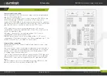
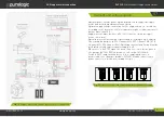
Connection is performed according to fig. 2 in XP10.
The driver allows to divide electronically physical stepper motor step –
1, 2, 8 and 16. Thus positioning accuracy is higher. Step division mode
is called microstep mode. This mode allows to reduce stepper motor
resonances at low revs. But when using microstep a claimed moment is
reduced on stepper motor shaft.
It is recommended to use the driver in step division 1:8 or 1:16. In these
modes stepper motor rotates as smooth as possible, low-frequency
vibrations are minimal and influence of stepper motor midfrequency
resonance is reduced.
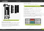
Switching step division mode of every channel is carried out according
fig.2 and fig. 8 by removable jumpers in adapters XP6 (channel №1),
XP7 ( channel №2), XP8 ( channel №3), XP9 (channel №4). Turn off
power device before making any settings.
Coil short-circuit module protection, wrong stepper motor connection
protection, protection against wrong stepper motor coil connection and
coils linked together / ‘+’ power supply.
In some cases by interturn short-circuit of stepper motor coil, short-
circuit protection may not work because there is no exceeding of
permissible alarm current.
This happens because under such coil short circuit resistance does not
equal 0 and the driver maintains the specified current.
Voltage jumps protection – the protection turns on when there is supply
voltage more than 30V, for driver protection against back EMF effect.
Protection functions, setup
11
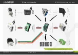
Fig. 8.
A scheme of stepper motor driver and voltage supply connection


