


Edition from 03.06.2015
13
PLC330.
Multichannel stepper motor driver
www.purelogic.ru
8 (800) 555 63 74
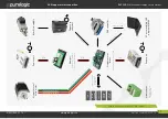
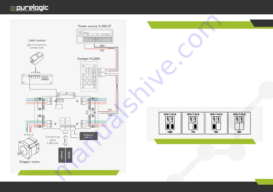
06. Stepper motor connection
Fig. 6.
Stepper motor and voltage power scheme connection
Maximal driver voltage power option depends on the applied stepper
motor and desired maximum rotation speed.
Optimal supply voltage calculation for the stepper motor is carried out
according to the formula U=32*v (stepper motor phase inductance mH),
but not more than 30V.
Supply current must be chosen 50...70% from the claimed stepper
motor coil current.
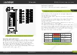
Operating current installation is performed according to fig. 2 and fig.
7 by removable jumpers in XP6 (channel №1), XP7 ( channel №2), XP8
(channel №3), XP9 (channel №4). Operating current installation must be
performed only when driver power supply is off.
When there is no STEP signal for more than 2 sec, each driver goes to
sleep mode (AUTOSLEEP) and reduces coil current till 300 mA.
For back EMF compensation device it is recommended to use a
protection device – dumper (module PLZ005). Module connection to
power source is carried out according to fig. 6.
Current and voltage option
07
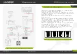
Fig. 7.
A scheme of connection stepper motor driver and voltage supply


