Page
40
Using MicroFlow PC
When connecting to the software using the RS485 connector, power to the sensor
can be obtained from the compatible Pulsar controller it is connected to.
With the two
MicroFlow
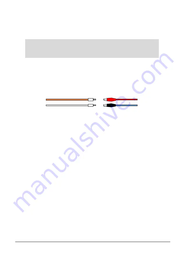
RS485 cables removed, connect the
Red
wire with the
Red
crocodile clip on the connector, to the
Orange
(RS485+) wire of the
MicroFlow
. And connect the
Blue
wire with the
Black
crocodile clip on the
connector to the
White
(RS485-) wire of the
MicroFlow
, as shown below:
Once the sensor is connected to the RS485 connector, insert it into the PC/laptop
ready for use, and ensure that your sensor is switched ‘ON’ to enable the software
to communicate with the sensor.
If you know the Com port that the RS485 connector is assigned to, please select
Setup
>
Serial Port
to enter the Com port number to the device. If you are not
aware of the Com port number, selecting ‘Connect to device’ will allow the
software to automatically search and connect to the RS485 connector Com port.
After launching the program and connecting to the
MicroFlow
, the device’s
parameters will be automatically extracted once a connection is established.
Once connected you can now view the information received from the sensor on
the Software’s individual tabs:
Flow
,
Flow Record
,
Trace
and
Parameters
.
Important Information
Ensure that power to the controller/sensor is switched ‘OFF’ before
removing cables and any connection is made.
MicroFlow RS485+
MicroFlow RS485-
RS485 Connector (-)
RS485 Connector (+)
Содержание MICROFLOW
Страница 1: ...MICROFLOW INSTRUCTION MANUAL...
Страница 2: ......
Страница 4: ......
Страница 6: ...58 59...
Страница 12: ...Page 6 EU Declaration of Conformity...
Страница 31: ...Page 25 Distance Distance Diagram 4 Diagram 3 Distance Distance Distance...
Страница 36: ...Page 30 This page is left blank intentionally...
Страница 44: ...Page 38 This page is left blank intentionally...
Страница 56: ...Page 50 This page is left blank intentionally...


