background image

www.pulsar.pl   


INTW   


8

4.5  STEP 3 – Setting the SSID for Wi-Fi network. 


Enter the network identifier, so that the RS485-WiFi interface will connect only with the designated router.  

To do that, log in to the router's configuration  interface: open a  web browser  window and type the 192.168.1.1  in 
the  address  bar  (default  router  address  after  the  reset  if  not  changed  previously)  and  confirm  by  pressing  the 
„ENTER” button. The page will be reloaded and the following window will be displayed: 


Fig. 6. The Wi-Fi router login window. 


To access the router configuration, log in with: 
 

Username:  

admin 


Password: 

admin 

Confirm by pressing the „Login” button. The adjustment window will be displayed 

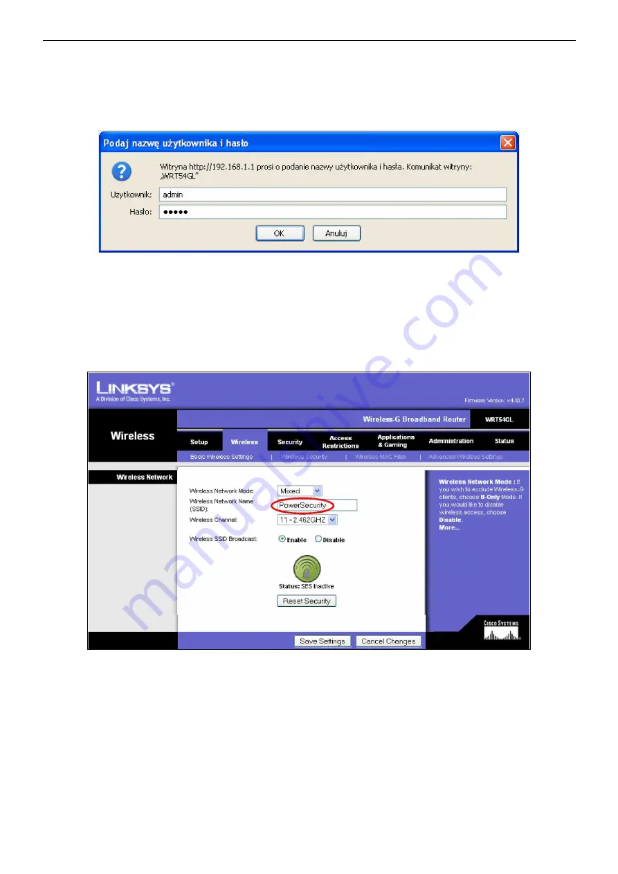
Select  the  „Wireless”  tab.  Next,  enter  the  SSID,  which  is  the  name  of  the  network  within  which  the Wi-Fi 

interfaces  will  be  transmitting  data  to  the  computer.  In  the  „Wireless  Network  Name”  field,  type  any  name  e.g. 
„PowerSecurity”. All other settings should be left unchanged. 


Fig. 7. The window of changing the network identifier. 


Confirm the changes by pressing the „Save Settings” button and then confirm by pressing „Continue”.  

This will reset the router. Meanwhile, temporary network loss can be observed, which will be indicated by blinking 
of  the  yellow  LED.  After  the  reset  of  the  router,  the  network  connection  will  be  restored  and  the  interface  will  no 
longer indicate problems, which will be indicated by permanent illumination of the yellow LED.  


Now, make the appropriate adjustments in the Wi-Fi interface configuration. 

Return to the „Digi Device Discovery” and double-click the line of the chosen interface. The window of the default 
web browser will be displayed. Log in correctly to configure the Wi-Fi interface.  
 

Содержание INTW

Страница 1: ...Interface WI FI v 1 0 CODE INTW EN Edition 3 from 05 12 2013 Supersedes the edition 2 from 19 12 2012 ...

Страница 2: ...Setting the serial port parameters 12 5 Configuration of power supplies 15 5 1 Configuration of power supplies of the PSBEN series with LCD display 15 5 2 Configuration of power supplies of the PSBEN series with LED display 16 5 3 Configuration of power supplies of the EN54 series with LCD display 17 5 4 Configuration of power supplies of the EN54 series with LED display 18 5 4 1 Setting the trans...

Страница 3: ... of the PSBEN or EN54 series with a PC in the Wi Fi network The PowerSecurity software enables remote monitoring of parameters through a cyclical preview of the current status of the power supply reading the event log and diagrams of currents and voltages and performing remote battery test The transmission range of Wi Fi network is approximately 30m inside buildings largely depends on its structur...

Страница 4: ... the enclosure of the power supply unit Therefore the power supply units fitted with Wi Fi interfaces can be freely arranged within the network without additional communication cables The role of the access point controlling the data flow is done by a Wi Fi router connected to a PC via an Ethernet network cable or wirelessly This type of communication is suitable for places where leading additiona...

Страница 5: ...he connection is lost for unknown reasons at any stage of the configuration process it is recommended to restore the factory settings of the router and the interface starting from the step 1 The information included in the following subsections show step by step how to configure the router and the Wi Fi interface assuming that both devices are set to factory settings settings after a reset The con...

Страница 6: ...the program will display the logged in Wi Fi interface Identification of our module can be done by comparing the MAC addresses Fig 3 Window of the Digi Device Discovery program showing a logged in Wi Fi interface The MAC address of the interface is located under the barcode of the DIGI module Fig 4 The MAC address located on the DIGI module In order to facilitate the further use of the devices in ...

Страница 7: ...e default gateway IP address should be left unchanged Before setting the network address make sure it is not used by any device on the network Confirm the changes by pressing the Save button The Digi Device Discovery application will display the message about the need to restart the interface which should be confirmed by pressing OK A reset progress window will be displayed From now on the router ...

Страница 8: ...f the network within which the Wi Fi interfaces will be transmitting data to the computer In the Wireless Network Name field type any name e g PowerSecurity All other settings should be left unchanged Fig 7 The window of changing the network identifier Confirm the changes by pressing the Save Settings button and then confirm by pressing Continue This will reset the router Meanwhile temporary netwo...

Страница 9: ...pressing the Login button The adjustment window will be displayed Fig 9 The interface configuration panel Choose the Network option from the Configuration group from the menu on the left side of the window Choose the WiFi LAN Settings at the bottom of the next window The following window will be displayed ...

Страница 10: ...button The Apply button cannot be omitted Choose the WiFi Security Settings tab at the bottom of the same window Settings from this tab are responsible for the protection against unauthorized connections In the Network Authentication and Data Encryption tabs choose this method of authentication and data encryption that is supported by the router Mark the WPA PSK and TKIP data encryption as they ar...

Страница 11: ...message informing about approved changes will be displayed The interface has been reprogrammed Reset the interface after reconfiguration of the router to make it operate accordingly to the modifications To do that switch to the router s configuration panel in the browser router might require re login to the page choose the Wireless menu and the proper Wireless Security tab Enter the same settings ...

Страница 12: ...erface and the router should be back the yellow LED is constantly illuminated 4 6 STEP 4 Setting the serial port parameters Once the connection between the Wi Fi interface and the router is established configure the communication channel between the Wi Fi interface and the power supply to which the interface is connected To do that switch to the interface configuration panel in the browser interfa...

Страница 13: ...elect Port Profile field and confirm by pressing the Apply button Fig 14 The interface configuration panel serial port parameters After reloading the page select the Basic Serial Settings tab at the bottom and enter the same settings as in the picture below Confirm by pressing the Apply button ...

Страница 14: ...15 2k 8E1 The changed values apply to all settings Fig 15 The communication parameters of the serial port Next choose the Advanced Serial Settings bar in the lower part of the window and enter the settings in the TCP Settings section as shown below Confirm by pressing the Apply button Fig 16 The interface configuration panel the TCP tab ...

Страница 15: ...are the same 5 Configuration of power supplies 5 1 Configuration of power supplies of the PSBEN series with LCD display The PSU fitted with LCD display enables setting the communication parameters of the serial port from the LCD panel To enter the setup mode press the SET button from the main screen use the or buttons to display the PSU menu confirm by pressing the SET button use the or buttons to...

Страница 16: ...t and leftmost buttons on the LED panel The Adr parameter will be displayed press the right arrow The trS parameter will be displayed press OK The display will show one of the two parameters 9 6 or 19 2 informing about the selected transmission speed use the or buttons in order to set the transmission speed to 19200 displayed as 19 2 confirm by pressing OK The trS parameter will be displayed again...

Страница 17: ...with LCD display enables setting the communication parameters of the serial port from the LCD panel To enter the setup mode press the SET button from the main screen use the or buttons to display the PSU menu press the SET button use the or buttons to display the Transmission menu The Transmission menu is at the bottom of the screen press the SET button the prompt will appear at the end of the lin...

Страница 18: ...ission speed simultaneously press the rightmost and leftmost buttons The tst parameter will be displayed use the or buttons to display the trS parameter press OK The information about the transmission speed will be displayed use the or buttons in order to set the required transmission speed 9 6k 115 2k factory settings confirm by pressing OK in order to return to the main menu simultaneously press...

Страница 19: ...ayed use the or buttons to display the trP parameter press OK The information about the parity of the transmission will be displayed on the panel use the or buttons in order to set the required communication mode 8N2 8E1 factory setting 8O1 confirm by pressing OK in order to return to the main menu simultaneously press the rightmost and leftmost buttons ...

Страница 20: ...ss 1 Fixed address Refresh period of the preview ms 100 60 000ms Refresh period of the parameters in the preview window CONNECTION Type Modbus RTU TCP IP TCP address 192 168 1 101 PSU network address Each Ethernet interface in the network has a unique address TCP port 2101 Response time ms 100 60 000ms The response time from the power supply interface The interval between the transmissions ms The ...

Страница 21: ...f the PSU Current consumption max 300mA TTL transmission speed Max 115200 bauds with parity check Wi Fi Transmission speed max 11Mbps Encryption WEP WPA WPA2 Indication LED lights Tx Rx PWR Operating conditions temperature 10 o C 40 o C relative humidity 20 90 Dimensions LxWxH 63 x 50 2 x 24 mm antenna Net gross weight 0 06kg 0 11kg Storage temperature 20ºC 60ºC ...

Страница 22: ... www zasilacze pl WEEE LABEL Waste electrical and electronic equipment must not be disposed of with normal household waste According to the European Union WEEE Directive waste electrical and electronic equipment should be disposed of separately from normal household waste WARRANTY 5 years from the production date WARRANTY IS VALID only upon presentation of the original invoice ...

Отзывы: