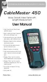


12
13
Shield Indicator
The “Shielded” icon, appearing in the fourth line of the LCD screen,
illuminates when a shielded data cable is properly wired at both ends. The
icon flashes if the shield is shorted to a pin in the cable. The shorted pins
display in the Wire Map and the “Short” indicator appears.
Wire Map: Tester Pin #
The top line in the Wire Map shows the pin numbers of the cables
connected to the main tester. If a cable fault is detected, the pin pairs
experiencing the error will flash.
Wire Map: Remote Pin #
The bottom line of the Wire Map corresponds to cables connected to the
remote tester. The Remote Pin # field will show if the connected cables
have errors (short, open, fail, and split). The appearance of dash lines
indicates shorted pins. No number displayed in the Remote Pin Number
line indicates Open pins. Pin pairs will flash if they are split.
Battery Low
The battery low symbol illuminates when the battery is nearing depletion.
The symbol flashes when the battery needs to be replaced.
Note:
Results may be unreliable at this point so the battery should be
replaced.
Location ID
The “ID” symbol, located in the third line of the LCD screen, appears when
the CableMaster is in Video, Data, or ID Mode. When using the wire
mapping remotes, the “ID” icon will turn on and the remote ID number will
display to its right. The ID number is not displayed if an error occurs, such
as “Open” or “Short”.
Voltage Detected Warning
If voltage is detected on any of the cable connectors, the “Voltage!” icon
flashes. A check for voltage is performed before each test and if found,
no test is run. If the icon appears, the tester should be disconnected im-
mediately from the source of the voltage. The tester automatically powers
down in 90 seconds if the detected voltage is not removed.


