2
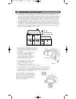
2.6: In rooms with open joists or beams,all
ceiling mounted alarms shall be located on the
bottom of such beams.
(See diagram “C”)
2.7: Alarms installed on an open-joist ceiling
shall have the smooth ceiling spacing reduced
to no more than half of the listed spacing
when measured at right angles to the solid
joist. (See diagram “C”).
MOBILE HOME INSTALLATION
Mobile homes built in the past five years have been designed to be energy efficient. Install Heat Alarms as previ-
ously outlined (refer to RECOMMENDED LOCATIONS and diagram A). In mobile homes that are not well insu-
lated compared to present standards, extreme heat or cold can be transferred from the outside to the inside through
poorly insulated walls and roof. This may create a thermal barrier which can prevent the heat from reaching an
alarm mounted on the ceiling. In such units, install the heat alarm on an inside wall with the top edge of the alarm at
a minimum of 300mm and a maximum of 600mm below the ceiling. (See diagram A).
If you are unsure about the installation in your mobile home, or if you notice that the outer walls and ceiling are ei-
ther hot or cold, install the alarm on an inside wall.
3. WARNING ! LOCATIONS TO AVOID
3.1 In front of air ducts used for heating and air conditioning, near ceiling fans, or other high air flow areas.
3.2
In an area where the temperature may fall below 5°C (41°F) or rise above 88°C (190.4°F).
3.3
Near fluorescent lights - electronic “noise” may cause nuisance alarms.
Diagram C
4. INSTALLATION INSTRUCTIONS :
“PLEASE READ CAREFULLY”
4.1 This Heat Alarm should be installed with an AS approved junction box. All connections must be
installed by a qualified electrician and be in accordance with the relevant requirements of the SAA
Wiring Rules AS3000 Standards and / or any other codes having jurisdiction in your area.
4.2 The appropriate power source is 240Vac 50Hz continuous single phase sine wave current supplied from a
non-switchable circuit which is not protected by a RCD.
4.3 This Heat Alarm must be mounted at a minimum height of 2 metres.
5. WIRING INSTRUCTIONS: FOR A.C. QUICK CONNECT HARNESS
5.1 For units that are used as single station,
DO NOT CONNECT THE WHITE WIRE .
Leave the
red wire insulating cap in place to make certain that the WHITE wire cannot contact any metal
parts.
5.2 When alarms are interconnected, all interconnected units must be powered from a single final sub
circuit.
5.3 A maximum of 24 devices may be interconnected only with smoke alarms of Models LIFESAVER
LIF5000, LIF5800, LIF5800RL, LANSD240I and Lifesaver Visual Signalling Strobe SL240.
CAUTION ! ISOLATE MAIN POWER TO THE CIRCUIT BEFORE WIRING THE
ALARM.
1004-7201-01(HA240)_V2:_ 2010.9.2 9:20 AM Page 3


