background image


INSTALLATION MANUAL: PAA29+ V 1.4 (07/2011) 


         27 


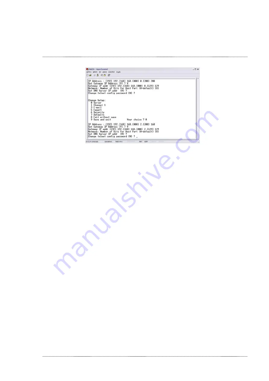
Figure 7.2D 


7.


Once  the  IP  is  configured,  the  option  “9”  allows  saving  the  new 
configuration. 

8.


The  PAA29+  IP  address  is  configured,  leave  the  jumpers  W3  and  W5 
(NET CONFIG) in the correct position depending on the connection that 
will be used. After that close the covers. 

9.


When  you  have  changed  the  IP  config  via  RS232,  you  can  open  the 
webpage of the device to continue with the installation easily. 

Содержание PAA29+

Страница 1: ...PAA29 v1 4 07 2011 INSTALLATION MANUAL PAA29...

Страница 2: ...aterna Valencia Spain Printed in Spain issue September 2009 This operating manual even in extracts may only be reprinted or otherwise copied with special written permission from Proyecson S A Editor r...

Страница 3: ...CONFIGURATION OF THE PAA29 ETHERNET PORT 20 7 1 OVER A TCP IP CONNEXION 20 7 1 1 CONFIGURE THE ETHERNET FOR A DOREMI SERVER 23 7 2 THROUGH A RS232 CONNECTION 25 8 SERVERS CONFIGURATION 28 8 1 SERVER S...

Страница 4: ...NPUT CONNECTION 47 9 5 1 INPUT WITH A NEGATIVE COMMON 47 9 5 2 INPUT WITH A POSITIVE COMMON 48 10 NOTES 49 10 1 FIRMWARE VERSIONS 49 11 ELECTRICAL PROPERTIES 49 12 DIMENSIONS 50 APPENDIX A SERIAL COMM...

Страница 5: ...ds of the distributor who installed it Always use original spare parts and accessories which must be installed by an authorized installer 1 2 INSTALLATION Do not handle the electrical system of the po...

Страница 6: ...jewelry which could get caught in the movable parts Always disconnect the power supply before cleaning or any kind of maintenance or repair Pull out the plug from socket do not pull from cable Keep c...

Страница 7: ...llel with existing film automation systems making it easy to switch between film and digital shows and even to run seamless presentations mixing both film and digital content Advanced features include...

Страница 8: ...input output PAA29 Rear Panel Connections General Purpose Inputs Eight opto isolated low voltage inputs screw terminals 24V logics General Purpose Outputs Twelve high current latcheable relay outputs...

Страница 9: ...entrally switched power source Dimensions and Weight 483 x 183 x 44 mm Environmental Conditions Operating 0 to 40 32 to 104 F 20 to 80 relative humidity non condensing Equipment manufactured by Proyec...

Страница 10: ...tive status led s The led indicate that the output is active Activate the outputs directly with the push bottoms without using the server Outputs will only remain active while keeping button pressed 5...

Страница 11: ...1 Mains input 100 230 vac 2 Inputs connector 3 Outputs connectors 4 RJ45 network connection port with connection and activity leds indicator 5 9 pin female D connector serial port 6 GPIO port with fem...

Страница 12: ...must be connected to a Dolby server through the port RS232 Configure Dolby server serial port and send receive commands as explained throughout this manual First configure PAA29 to activate the serial...

Страница 13: ...pers W3 and W5 of NET CONFIG in the position TX_S and RX_S respectively as shows figure 6 1B Figure 6 1 B 3 Put back the PAA29 top cover and connect it to the Dolby DSS100 or DS200 through the RS232 s...

Страница 14: ...INSTALLATION MANUAL PAA29 V 1 4 07 2011 14 See the interconnection diagram on the following picture Figure 6 1C...

Страница 15: ...er as a new device and the send receive commands configured as explained throughout this manual First set up the PAA29 in order to enable the Ethernet port To do this open top cover and set the jumper...

Страница 16: ...7 2011 16 Put back top cover device and connect PAA29 to the Ethernet Switch of Doremi s server network use a cable CAT 5 or higher with a pin to pin configuration See the interconnection diagram on t...

Страница 17: ...l port if the server has a 2 0 5 0 or higher software version configuring the PAA29 to activate the serial port as followed 1 Open top cover and set the jumper to config 1 position in the W4 configura...

Страница 18: ...1 18 3 Put back the PAA29 top cover and connect it to the Doremi server through the RS232 serial port use a DB9 pin to pin serial cable You need to add the PAA29 as a serial device The connection diag...

Страница 19: ...are using the server s GPIO port There is no need to set up the PAA29 with this kind of connection due to the fact that the PAA29 operates as a power interface and isolation of the GPIO server port T...

Страница 20: ...connect with it using the RS232 port to verify or modify the IP To configure the Paa29 over Ethernet follow this instructions 1 Connect the PAA29 to an Ethernet switch as well as the PC that will be u...

Страница 21: ...nd the page appears just like the Figure 7 1B if the PAA29 is a factory device the data on the window will be the same ones as shown on the figure In the section IP Address write the address for the P...

Страница 22: ...gure 7 1B 6 Once done choose the Menu option Apply Settings and a page appears just like the Figure 7 1C which will indicate that the data have been saved and that the device is being rebooted in orde...

Страница 23: ...igured in order to allow communication with the PAA29 7 1 1 CONFIGURE THE ETHERNET FOR A DOREMI SERVER 1 Open the Paa29 configuration webpage and configure the Network as in the previous step 2 When y...

Страница 24: ...ALLATION MANUAL PAA29 V 1 4 07 2011 24 Figure 7 1 1A 7 Click on the OK button to confirm the changes 8 Click on the Apply Settings to save the changes and reboot the network system as in the previous...

Страница 25: ...the figure 7 2A Figure 7 2A 2 Connect the PAA29 serial port with the serial port of a PC through a pin to pin cable 3 Open a terminal program to work with COM ports Configure the serial port in order...

Страница 26: ...essing the key enter appears the information of the port current configuration and the menu that enables modifications figure 7 2C Picture 7 2C 6 Entering the 0 option allows to change the IP and the...

Страница 27: ...configuration 8 The PAA29 IP address is configured leave the jumpers W3 and W5 NET CONFIG in the correct position depending on the connection that will be used After that close the covers 9 When you...

Страница 28: ...gure the server in the PAA29 follow the next steps 1 Open the PAA29 2 Configure the selection jumpers following the instruction already described in the CONNECTION PROCEDURE section 3 Close the PAA29...

Страница 29: ...the configuration box serial command settings write 0D in the configuration box termination and leave the configuration box reset in blank as you can see in the figure 8 2B example Figure 8 2B 6 Save...

Страница 30: ...name do the modification and save the changes There is a possibility that the name doesn t appear in the CONTENT menu of the server therefore reboot the server Figure 8 2C 11 To modify the type of th...

Страница 31: ...rver 2 Start the Device Manager by accessing through the Menu Doremi Labs Inc Device Manager 3 Click on the icon Add in order to add a device 4 On the appearing pop up window select the device Raw as...

Страница 32: ...nfiguration on the figure 8 3 1B 10 Click on the icon Save in order to save the new device Figure 8 3 1B 11 If you are not logged as admin you will need to be authenticated Figure 8 3 1C Figure 8 3 1C...

Страница 33: ...o this the first one is to add the output cues only valid for output cues not for trigger cues following the Doremi Macro Editor Manual To do it in this way please follow the next steps 1 Create a new...

Страница 34: ...on table from APPENDIX B COMMANDS ASCII FOR DOREMI SERVER You must write the codes exactly as in the table otherwise the PAA29 may not recognize them 5 You can see an example of this from in the Figu...

Страница 35: ...INSTALLATION MANUAL PAA29 V 1 4 07 2011 35 Figure 8 3 2 D 8 If the command is successfully received for the Paa29 a pop up message like the one in the figure8 3 2 E is shown Figure8 3 2 E...

Страница 36: ...29 with the Doremi server To do it you must follow these steps 1 Connect a pc or laptop to the same network where you have the Doremi server connected To ensure that they are in the same network you c...

Страница 37: ...ow you can set up the output cues taking the commands from this library 4 The procedure to create automation cues using the library is very similar as the one without use it but very much simple First...

Страница 38: ...button as you can see in the figure 8 3 3D The keys for the action are these The actions from H1 to H12 activate High and maintain active the corresponding output The actions from L1 to L12 deactivate...

Страница 39: ...me Select Paa29 Message Type Select Text Message Left untouched it comes from the Paa29 library previously selected Figure 8 3 3E 10 Once the required macros are added save the changes and then use th...

Страница 40: ...3 chapter of this manual you can see the procedure to load the file and create the Paa29 Library With this file loaded you can create trigger cues following these steps 1 Open the Doremi Macro Editor...

Страница 41: ...me field Figure 8 3 4C Figure 8 3 4C 4 Pressing this button you will open the Signal Library pop up window you must select the Paa29 in the driver window and choose the appropriate input of the Paa29...

Страница 42: ...e for the Input 1 in the figure 8 3 4E Click on the Ok button to finish the creation of the trigger cue Figure 8 3 4E 6 Finally in the Doremi Macro Editor main screen you can save the trigger cues con...

Страница 43: ...V 1 4 07 2011 43 9 OUTPUTS INPUTS OF THE PAA29 The contacts order in the connectors and the internal circuitry of the PAA29 outputs as shown on the following schemes and pictures 9 1 OUTPUT 1 CONNECTO...

Страница 44: ...INSTALLATION MANUAL PAA29 V 1 4 07 2011 44 9 2 OUTPUT 2 CONNECTOR Figure 9 2A Picture 9 2B...

Страница 45: ...INSTALLATION MANUAL PAA29 V 1 4 07 2011 45 9 3 OUTPUT 3 CONNECTOR Figure 9 3A Figure 9 3B...

Страница 46: ...INSTALLATION MANUAL PAA29 V 1 4 07 2011 46 9 4 INPUT CONNECTOR Figure 9 4A Picture 9 4B...

Страница 47: ...OF INPUT CONNECTION The digital inputs are divided in two groups each group shares a common independent cable The first group includes the inputs from I1 to I4 and in the second one the inputs from I5...

Страница 48: ...INSTALLATION MANUAL PAA29 V 1 4 07 2011 48 9 5 2 INPUT WITH A POSITIVE COMMON Picture 9 5 2A...

Страница 49: ...version PNA O4 o Fully compatible with Dolby DSS200 and DSS100 DSP100 servers using the serial port o Fully compatible with the Doremi DCP200 and DCP2K4 servers automation using a UDP IP Ethernet conn...

Страница 50: ...INSTALLATION MANUAL PAA29 V 1 4 07 2011 50 12 DIMENSIONS Dimensions and Weight 483 x 183 x 44 mm...

Страница 51: ...Output Other P06 56U56UF Pulse Output 6 Output Other P07 57U57UG Pulse Output 7 Output Other P08 58U58UH Pulse Output 8 Output Other P09 59U59UI Pulse Output 9 Output Other P10 5AU5AUJ Pulse Output 1...

Страница 52: ...put 2 Output Lights L03 73U73U0 Off Output 3 Output Lights L04 74U74U1 Off Output 4 Output Other L05 75U75U2 Off Output 5 Output Other L06 76U76U3 Off Output 6 Output Other L07 77U77U4 Off Output 7 Ou...

Страница 53: ...ulse Output 8 Output P09 59U59UI r Pulse Output 9 Output P10 5AU5AUJ r Pulse Output 10 Output P11 5BU5BUK r Pulse Output 11 Output P12 5CU5CUL r Pulse Output 12 Output H01 61U61UM r On Output 1 Output...

Страница 54: ...Output L04 74U74U1 r Off Output 4 Output L05 75U75U2 r Off Output 5 Output L06 76U76U3 r Off Output 6 Output L07 77U77U4 r Off Output 7 Output L08 78U78U5 r Off Output 8 Output L09 79U79U6 r Off Outp...

Отзывы: