background image

Lynx.GX Installation and Management 


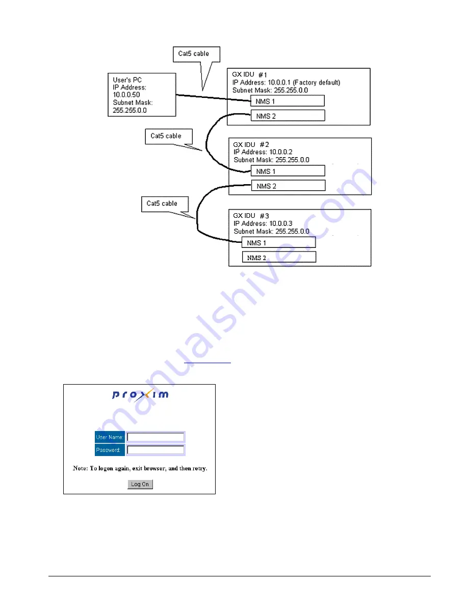
Figure 4.  Daisy Chaining NMS Connections at a Hub Location 

The next few pages describe how to access the Web Interface and the configuration and management 
available. 

Initial Log-On 

To access the Web Interface: 

1.  At your browser address field enter 

http://10.0.0.1

 (or your previously set IP address) to open the 

Logon


window. 


Chapter 3.  Managing the Lynx.GX 

34


Содержание Lynx.GX 16T

Страница 1: ...Part Number 64352v1r2 Lynx GX Installation and Management Models 4T 4E BNC 4E 8T 8E 16T ...

Страница 2: ...s A digital device pursuant to part 15 of the FCC Rules These limits are designed to provide reasonable protection against harmful interference when the equipment is operated in a commercial environment This equipment generates uses and can radiate radio frequency energy and if not installed and used in accordance with the instruction manual may cause harmful interference to radio communications O...

Страница 3: ...or removing any covers you could expose yourself to hazardous energy parts Incorrect reassembly of this product can cause a malfunction or electrical shock when the unit subsequently is used Insert any objects of any shape or size inside this product while powered Objects could contact hazardous energy parts resulting in a risk of fire or personal injury Spill any liquids of any kind on or inside ...

Страница 4: ...ons 48 Equipment Co Location 52 Planning for and Selecting IF Cable 53 Planning for Antenna and RF Transmission Line Installation 54 APPENDIX B WEB INTERFACE WINDOWS AND FIELD DESCRIPTIONS 56 Device Tab Accessing Radio Information 56 Interface Configuration Tab Modifying T1 E1 Interface Configurations 57 System Configuration Tab Configuring Tx Power Security Link ID and Tx Channel Plan 58 Status T...

Страница 5: ...SUPPORT 100 Enhanced Warranty Packages 100 WARRANTY 101 ACRONYMS GLOSSARY 103 FIGURES Figure 1 Back to Back Test Configuration 12 Figure 2 Link Testing 13 Figure 3 Loopback Mode 13 Figure 4 Daisy Chaining NMS Connections at a Hub Location 34 Figure 5 Port Connector Layout for 16 T1 Ports 75 Figure 6 VF Plug Pin Assignments 76 Figure 7 Aux Plug Pin Assignments 77 Figure 8 NMS Plug Pin Assignment 78...

Страница 6: ...ook is designed for network engineers and field service personnel responsible for installing maintaining and troubleshooting the Lynx GX radios It is assumed you have an understanding of networks in general and a basic understanding of the following subjects Microwave fundamentals Antenna systems Transmission line systems Electrical grounding Microwave test equipment T1 E1 DS 3 Ethernet Fast Ether...

Страница 7: ...ission line connector terminations º Best way to test is a return loss measurement VSWR º Basic function can be tested using a continuity and short test with DMM º The transmission line can be evaluated with a network analyzer connected to both ends of cable through the cable and comparing when spectrum analyzer is connected directly to the radio without the cable º Transmission line loss can be e...

Страница 8: ...g any D type connector Adjustable 6 wrench to attach the chassis ground wire 7 16 for RFU and for IDU No additional tools are required from the above list if the RFU is mounted indoors RF Unit Installation Tools Outdoor You must obtain the following before installing the RF Unit outdoors RFU outdoor mounting kit NOT INCLUDED WITH SHIPMENT order separately Adjustable 6 inch wrench for installing th...

Страница 9: ...on to location Shipment Contents Each Lynx GX shipment includes one GX Indoor Unit IDU one GX RF Unit RFU and an installation accessory kit as shown in the tables below RF Unit Indoor Unit Lynx GX 4xT1 Lynx GX 4T 5 8 GHz ISM System Hi Model 51850 10H0 Item 62292 Low Model 51850 10L0 Item 62291 Item Description Item Description 62290 Lynx GX 4T1 Indoor Unit 62290 Lynx GX 4T1 Indoor Unit 62138 Lynx ...

Страница 10: ...X RFU Indoor Installation Kit 67263 GX IDU Installation Kit 67263 GX IDU Installation Kit Lynx GX 8xE1 Balanced RJ48C Lynx GX 8E1 5 8 GHz ISM System Hi Model 301 51145 20H0 Item 62145 Low Model 301 51145 20L0 Item 62144 Item Description Item Description 62143 Lynx GX 8E Indoor Unit Balanced RJ48C 62143 Lynx GX 8E Indoor Unit Balanced RJ48C 62138 Lynx GX 5 8 GHz Hi RF Unit 62137 Lynx GX 5 8 GHz Low...

Страница 11: ...unt Brackets 2 inch Extender Brackets GX Rack Mount Screw Pack see below 2 2 1 GX Rack Mount Screw Pack Rack Mount Screws Small Extender Bracket Screws 4 8 Custom Cable Kit RJ 45 RJ 45 Connectors 2 Custom Cable Kit DB9 Metal DB9 Connectors DB9 Cable Sheaths 1 1 STEP 3 TEST RADIOS BACK TO BACK Before installing the radios Proxim recommends a back to back test of the radio pair Back to back testing ...

Страница 12: ...errors are still present one or both of the radio terminals is likely to be faulty Figure 1 Back to Back Test Configuration It can be helpful to insert a variable RF attenuator between the radios to fade down the path to determine that the threshold specification is being met You can run the threshold tests in both directions to isolate the radio problem if any See Link Testing on page 13 for more...

Страница 13: ...ine interface is in loopback to the line connector does not test the wireless link This is useful for external equipment or circuit testing including an external BER tester Remote LB int The far end or remote radio is set to loopback data The radio uses an internally generated signal and external signals are ignored This is useful for testing the entire radio link without using external test equip...

Страница 14: ... corner For rack mounting to optimize cabling and to avoid interference with the RFU or antenna cables mount the IDU high in a standard 19 inch rack Empty rack mounting spaces above and below the unit are recommended especially if the surrounding equipment dissipates a considerable amount of heat over 40W When mounting both the IDU and the RFU indoors mount the IDU immediately below the RFU with n...

Страница 15: ...IDU using the long mounting screws that are contained in the GX Rack Mount Screw Pack The following figure illustrates mounting bracket attachment for the IDU only occupying one space in a 19 inch rack 1 Attach brackets to unit 2 Attach brackets to 19 rack Attach the L RFU Rack Mount Brackets to each side of the RFU using the long mounting screws that are contained in the GX Rack Mount Screw Pack ...

Страница 16: ...g figure 5 Insert two screws and lock washers appropriate for your rack into each of the mounting brackets and tighten IMPORTANT When the RFU is rack mounted it must be mounted directly above the IDU and facing with the connectors forward in the same direction as the connector panel of the IDU as shown The IDU fan exhaust is used to cool the RFU in a rack mount configuration Also if one unit is pr...

Страница 17: ... If the RFU is mounted outdoors on both ends of the link you must order two outdoor mounting kits 2 To facilitate assembly installing the carriage bolts to the top holes of the RFU can be partially completed on the ground before being raised to the pole assembly Installing the Mounting Plate 1 Obtain the optional GX RF UNIT Outdoor Mounting Kit Proxim part ACC GX RF 2 item number 61688 2 Hold the ...

Страница 18: ...l the connectors using weatherproofing material A short jumper cable can be used to connect the IF DC lightning arrestor if necessary The lightning arrestor must be properly grounded 7 Attach a grounding wire to the ground post of the RUF and route to a proper low impedance ground point Wire of at least 10 AWG should be used a braid or strap conductor is the preferred choice STEP 5 INSTALL AND ADJ...

Страница 19: ...s have not synchronized however you cannot measure far end RSL from the near end terminal until the units are synchronized Aligning the Antenna The larger the antenna the more critical alignment becomes For example with a 2 foot dish at 5 8 GHz the antenna can be moved 3 degrees off the correct heading before the receive signal level drops by 3 dB This compares with a 6 foot dish which can be move...

Страница 20: ... LED Descriptions on page 73 When aligning antennas if the RFU is located indoors or distant from the antenna location you may want to run wires or a cable from the RSL test point on the RFU to the antenna location so that the voltmeter reading or audio device is directly visible and audible to the technicians aligning the antenna Alternatively º The RSL value can be provided by a verbal relay or ...

Страница 21: ...ee receive signal level is 20 dBm the receiver can produce errors above this level however this level will rarely if ever be exceeded in an actual system implementation See Calculating Received Signal Level and Link Budget on page 51 to calculate the anticipated RSL However if cabling the system back to back with inadequate attenuation permanent damage can occur Also extremely short paths can resu...

Страница 22: ...use 90 degree adapters unless rated at operating frequency Test power voltages and pinouts at the power connector before connecting power to IDU Connecting an Antenna The radios are equipped with an N type female connector on the RFU at the antenna port You can use a short length jumper cable such as 1 4 inch to 1 2 inch coax or pigtail of approximately 6 feet in length fitted with two N type male...

Страница 23: ...securing the transmission line to the antenna structure as the length is likely to be very short In this configuration Proxim recommends you place an RF lightning suppression device specified for use at 5 8 GHz such as Polyphaser LSX between the RF transmission line and the RFU s RF port as close as possible to the RFU Always properly ground any lightning suppression device When the RFU is mounted...

Страница 24: ...ery 100 feet 5 Install lightning protection devices including proper grounding and termination to cables There should always be a lightning protection device at the egress point for whatever cables egress the building or enclosure For an all indoor implementation the in line lightning protection device must be rated for the operating frequency of the radio 5 8 GHz Lightning protection for the RFU ...

Страница 25: ...m the left column lights up red then the bottom one flashes red If these conditions continue after one minute there is a problem powering up the radio and the unit should be returned There can be up to 200mW of RF power present at the RFU antenna port Before power is applied Terminate the antenna port either by connecting the RFU to an antenna or to an appropriate 50 ohm load such as provided by a...

Страница 26: ... If using positive power connect the positive voltage to pin 3 Connect the return connection to pin 1 and use an optional jumper to pin 2 for ground reference The ground connection is available using pin 2 Do not ground both sides of the power supply Proxim recommends you leave the ground connection floating if the power supply also is floating This configuration can help avoid ground loops and pr...

Страница 27: ...e government agencies or Proxim Corporation if there is any question regarding maximum output power allowed Using the Web browser interface through the NMS1 or NMS2 port you can adjust the output power from factory settings Select the Sys Cfg tab and choose from 5 to 25 dBm in 1 dB steps in the Tx Power dBm field Note For precise measurement of transmitter power a calibrated RF power meter is reco...

Страница 28: ...and the absolute voltage on all pins Verify ground connection for power if applicable Ensure that the RF Antenna port connection is properly terminated before applying power Ensure that the IDU to RFU cable is connected 4 Connect power to the radio When the radio is initially powered on some alarm conditions may be present This is normal and alarms can be ignored at this time 5 Ensure that the ant...

Страница 29: ...ve not been finely aligned the RSL value at this time will not be the desired value However you can verify that some communication is taking place between the two units Use the RSL voltage reading to align the antennas Align one antenna at a time as discussed in Alignment Guidelines on page 19 Align both ends of the link before proceeding The RSL voltage output on the radio s front panel supplies ...

Страница 30: ...pters improper termination Path obstructions trees buildings hills and so on Improper path clearance line of sight earth curvature Fresnel zone diffraction and partial obstruction Weather inversion layers ducting and multipath Antenna feed coaxial connector problem Highly reflective surfaces of the path terrain 8 Verify the channel plans Verify that the units follow the same channel plan and that ...

Страница 31: ... either telephone can be used to dial up the far end location The far end radio internal ringer and the connected telephone ring and if answered two way full duplex voice communication is established If the radios are connected in a repeater configuration you can establish orderwire services in the network by connecting the radios by cabling their front panel VF connectors The orderwire operates o...

Страница 32: ...cation The MIB is available from Proxim Technical Services or the Proxim Internet site http www proxim com support For more information see Management with SNMP on page 44 Telnet Command Line Interface CLI through IP If a terminal is not available or you are a distance from the radio you can use Telnet See Management with Telnet on page 44 Each radio s IP address is used to identify it for the Web...

Страница 33: ...s Note The PC connected to the near end radio s NMS port must be on the same subnet as the near end radio to communicate with each other Change both the near end and the far end radio to the desired IP addresses You may need to change the subnet of your PC many times to accomplish this as you change from the default IP address to your desired address scheme Always save the new IP address configura...

Страница 34: ... The next few pages describe how to access the Web Interface and the configuration and management available Initial Log On To access the Web Interface 1 At your browser address field enter http 10 0 0 1 or your previously set IP address to open the Logon window Chapter 3 Managing the Lynx GX 34 ...

Страница 35: ...hoose to view LED information for the near end radio the unit to which you are connected or the far end radio The default option when you open a tab or refresh a page is to display the near end LEDs If the far end radio is not available when you choose to view far end LEDs these LEDs flash red See Front Panel LED Descriptions on page 73 for more information In addition the large green bar at the v...

Страница 36: ...The following is an example of two browsers enabled for two different radios The browser for each radio is opened using the IP address of that radio Setting Up Static Route for Remote Access to Far End Radio To access the far radio from a near side computer set that computer s default gateway to 10 0 0 1 or configure a permanent static route on your computer to access the 10 10 0 0 network through...

Страница 37: ...uration of the far end radio from the near end radio This is not a recommended means to manage the radios Helpful Configuration Hints You must set Tx Power to meet required EIRP limits or RSL requirements You must set IP Address and Subnet Mask to conform to your network You also must set the Default Gateway Address if your monitoring stations will be on a different IP subnet from the GX radio If ...

Страница 38: ...te DEVICE RSL reading of radio over time STATUS RSL button Elapsed time since reset STATUS RSL current STATUS Errored seconds STATUS RSL max STATUS External Input Alarm ALARMS RSL min STATUS Fan summary alarm ALARMS RSL min timestamp STATUS IDU serial number DEVICE Severely errored seconds STATUS IDU temperature STATUS Spectrum Analyzer ADMIN Interface type DEVICE Status alarms all or selected LOG...

Страница 39: ... and serial numbers data rate and frequency interface type and software version levels The fields in this window are not configurable Modifying T1 E1 Channel Interface Configurations Intf Cfg Tab on page 57 Modify the T1 or E1 channel interface configurations including line build out line code and loopback configuration Chapter 3 Managing the Lynx GX 39 ...

Страница 40: ...t and temperature You also can track the RSL reading of the radio over time by clicking the RSL Log button on the Status window The fields on this window are not configurable See RSL Log on page 60 for more information Configuring System Parameters Sys Cfg Tab on page 58 Configure Tx power orderwire address security link ID aux port speed RF frequency settings and External Alarms Chapter 3 Managin...

Страница 41: ... the built in Spectrum Analyzer to check for transmission sources that the radio can receive and to determine whether these emitters could be a source of possible interference click the Spectrum Analyzer button on the Admin window Monitoring Link Alarms Alarms Tab on page 61 Monitor link status both near end and far end link alarm status The orientation of the alarms matches the position of the co...

Страница 42: ... on page 62 View all or selected status and alarms for the radio You can view alarms of all levels or selected levels and greater Viewing Proxim Support Information Contact Tab on page 64 View Proxim Support information see Technical Support on page 100 Chapter 3 Managing the Lynx GX 42 ...

Страница 43: ...r for reference The radio has two banks of flash memory available Bank 0 and Bank 1 Only one bank is in use at a time After uploading the radio automatically switches to the bank holding the newly uploaded software Once software upload is complete the following message is displayed File upload finished and system will reboot Restart browser to logon again You will need to wait one minute for the r...

Страница 44: ...IBs contain all the traps and configuration variables for the radio SNMP agent These MIBs are included in the CD that ships with the unit Network Connections Use a ping utility to make sure your SNMP Manager can communicate with the radios Configure the radio s SNMP Community strings using the Web interface Admin page or through the CLI interface These radios support many of the RFC1213 functions ...

Страница 45: ...monitor the radio link at regular intervals to ensure that the link conditions are not changing When visiting a radio site for maintenance you should check the following items and record the results RSL voltage Power setting NMS Far end RSL voltage Alarm conditions Be sure to verify that the unit has adequate ventilation If any alarm conditions exist record them See Troubleshooting Alarms on page ...

Отзывы: