


Lynx.GX Installation and Management
Helpful Hints—Checking RSL Against Predicted Results
▪
Is the RF Link LED red?
º
If so, keep aligning the antennas.
º
If not (or green), the radios are talking!
▪
Does the measured RSL at both ends closely match the predicted value?
º
If too strong, this is probably OK; the transmitter power may be higher than originally planned.
º
If not strong enough, keep aligning.
º
If still not strong enough, double-check the prediction and compare to the actual installation (verify
antenna gains, lengths/type of transmission line, path length, and so on).
º
Are you sure you have line of sight?
º
Did you test the radios in advance?
º
You could have a bad cable, connector termination, or antenna
▪
Do you need to adjust the output power down?
º
Check path calculations and regulations.
º
Re-verify RSL after power is adjusted.
Several factors can contribute to low RSL:
▪
Incorrect antenna alignment (aligned on a side lobe and not on the main signal)
▪
Improper polarization orientation of antennas (horizontal versus vertical)
▪
Transmission line problems (loose connections, kinked or damaged cables, “loss-y” adapters, improper
termination)
▪
Path obstructions (trees, buildings, hills, and so on)
▪
Improper path clearance (line-of-sight, earth curvature, Fresnel zone, diffraction, and partial obstruction)
▪
Weather (inversion layers, ducting, and multipath)
▪
Antenna feed (coaxial/connector) problem
▪
Highly reflective surfaces of the path terrain
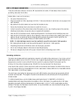
8) Verify the channel plans.
Verify that the units follow the same channel plan, and that the opposite Tx and Rx frequencies complete a
matched pair of radios (for example, A1 and A2 make up a matched pair). The RFU pair is made up of a “Hi”
and “Low” pair of the same root model number. Also, if co-locating equipment for multiple paths, make sure that
you do not deploy the same transmitter frequency as any of the receive frequencies at the same site.
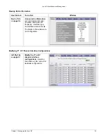
9) Connect unit to telecommunications equipment to pass the T1/E1 traffic.
Connect to the T1 circuits using properly shielded 8-pin modular (RJ-48C) connectors. Connect to the E1
circuits using properly shielded 8-pin modular (RJ-45) connectors.
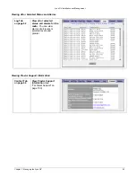
All front panel LEDs should either be off or green. (You may need to set Data Input parameters on the HTTP
IntfCfg
page to make the Data Input LED green.) If any LEDs are red, see “Front Panel LED Definition” on
page 73 or “Troubleshooting Alarms” on page 95 for more information.
Chapter 2. Installing the IDU and RFU
30