background image

CT-3400 TW 

Installation Guide 

P.17


Secure Lock 

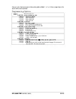
This feature allows the module to control certain OEM factory alarm systems without requiring the 
use of other wires for disarming the OEM alarm. (Namely, this feature is designed for OEM 
systems that use the factory lock wire to arm the alarm and the unlock wire to disarm it.) 

Standard Secure Lock 

If this Option is selected, upon receiving a remote 

START

 signal, secure lock will 

UNLOCK


the doors 

(disarming the factory Alarm); 1/2 sec. after remote start it will 

re-lock 

the doors. 4 seconds after 

shutdown, secure lock will 

re-lock 

all doors (

arming 

the system once again). 

Please note 

that 

most OEM systems will 

not 

rearm the alarm while the engine is running, but 

will 

lock the doors. 

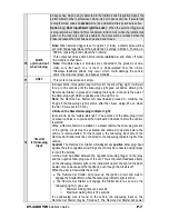
Smart Secure Lock 

If the vehicle is initially locked, at remote 

START

 the Module will send an 

UNLOCK/Disarm


pulse before 

start-up, 

LOCK/Arm


again when the engine is running, and 

LOCK/Arm


once again 4 sec. after it shuts 

shut down the engine. 
If the vehicle is initially unlocked, upon remote start the module will start the engine and arm the 
starter kill, but the doors will not be locked or unlocked at any moment of the sequence. 

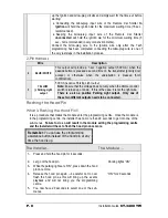
Priority Door Access  

(Both 

AUX

 1


and 

AUX 2


can be programmed for Priority Door Access.)

 This great feature allows 

the user to 

UNLOCK


solely the driver’s door with a single press of the 

UNLOCK


button on the 

transmitter, and to 

UNLOCK


the other doors, if desired, by pressing the 

UNLOCK


button for a second 

time. 
The output will provide a 1-sec negative output when the 

UNLOCK


button is pressed a second time 

on the transmitter. This can be used not only as priority door access, but also as trunk release. 

The AUX 2 Timed Output 

This 500 mA negative 

AUX 2

 output can be used for many different applications. It can be 

programmed for priority door access if 

AUX 1


is programmed for horn confirmation. 

To activate the 

AUX 2


output, press 

and then 

LOCK


button. 

The AUX 3 / Trunk or Sunroof Output 

This 500 mA negative 

AUX 3

 output can be used for many different applications. The output can be 

programmed to give a 1-sec. pulse when the 

TRUNK


button is pressed (if the ignition is 

OFF


or when 

Ignition is 

ON


after a remote start) or to give a continuous output as long as the 

TRUNK


button is held 

down (for sunroof or window control). 

Note 

In Trunk mode, the output will operate only if the Ignition is 

OFF 

or if the 

engine is running under the control of the module. 
If 

AUX 3

 is programmed for a 1-second 

TRUNK

 signal, you will need to hold the 

TRUNK

 button down for 3 seconds in order to activate the trunk. 

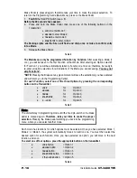
Trunk 2 Output with Disarm / Rearm Pulse 

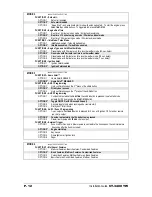
When the Trunk 2 Option is selected (Mode 3, Function 4, Option 3), a Disarm pulse will be sent 
before the trunk is popped. An arm pulse will be sent 4 seconds later. This option is overridden 
when the 

Zone 3 Bypass 

is used as a trunk pin (Mode 3, Function 5, Option 1). 

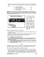
Programmable External Trigger 

The External Trigger wire can be connected to a trunk pin-switch generating a negative signal 
when the trunk is open. 

Содержание CT-3400 TW

Страница 1: ...ear select lever is in the Drive position If the vehicle starts in gear install a manual transmission car starter instead DOC 2 53 CT 3400TW September 4 2007 MO Assembled in Canada A U T O M A T I C T R A N S M I S S I O N M U L T I C H A N N E L T W O W A Y L C D R E M O T E S T A R T E R S Y S T E M W I T H V I R T U A L T A C H S Y S T E M A S P R G 1 0 0 0 C O M P A T I B L E CT 3400 TW Instal...

Страница 2: ...er Features of the Module 18 Fifth Relay Output 2nd IGN or 2nd fcACC or 2nd START 18 Multi car Operation 18 Resetting the Module without the Plug in valet button 19 Resetting the Module with the Plug in valet button 19 Troubleshooting Poor Transmitting Range 19 Testing 21 Closing Up 21 Diagnostics Parking Lights 22 Installation Order 23 A basic introduction to the Relay 25 Troubleshooting Q A 29 I...

Страница 3: ...io interference to other users the antenna type and its gain should be so chosen that the equivalent isotropically radiated power EIRP is not more than that required for successful communication NOTE The manufacturer is not responsible for any radio or TV interference caused by unauthorized modifications to this equipment Such modifications could void the user s authority to operate the equipment ...

Страница 4: ...F Parking Light flashes referred to in this manual refer to the Parking Light output of the Module and not that of the vehicle Harness Description 6 Pin Main Ignition Harness a k a the primary harness The two Red wires are the power inputs for the module the other wires are for recreating the actions of the Ignition switch during remote starts On most vehicles these wires are connected at the vehi...

Страница 5: ...e erratic problems 2 PURPLE AC Tachometer input This wire tells the Module if the Engine is running or not It requires at least 1 8 volts AC and 1 5 Hz or faster at idle Common Tach references are the negative side of an injector the negative side of an Ignition Coil Camshaft sensor Crankshaft sensor or the Engine Control Module ECM Note A Tach signal that is too low will cause the Module to over ...

Страница 6: ...cted to a Single Pole Double Throw Relay This wire will connect to Pin 85 on the Relay and Pin 86 will be connected to the Ignition wire A second benefit of the Starter Kill is the Anti Grind feature When the vehicle has been remote started the Anti Grind prevents the starter motor from re engaging when the ignition key is inserted in the Ignition switch and accidentally turned to the CRANK positi...

Страница 7: ...the Light is on Note the Remote Car Starter will nevertheless proceed to cranking the Engine if the Glow plug Light is still on after the 18 sec delay 25 sec when the Run Time is set to 30 min A Note on the Diesel Glow plug Indicator Light Also known as the wait to start light The purpose of the Glow plug circuit on diesel vehicles is to pre heat the Combustion Chamber before the vehicle is starte...

Страница 8: ...ut Note Ensure that the voltage does not vary when the dimmer control switch is turned up or down If this is the case it is not the right wire There is a also a positive Parking Light output Only one of these two different outputs needs to be connected Flashing the Hood Pin What is Flashing the Hood Pin It is a procedure that makes the module enter the programming centre Once the module is in the ...

Страница 9: ...after the wiring of the Module is completed The Module has the ability to retain up to 4 different Transmitter codes if a fifth Transmitter is programmed the code of the first Transmitter will be erased from memory How to Program the Transmitter 1 FLASH the Hood Pin Switch see p 8 Before the 20 seconds have passed turn the Ignition Key to the IGNITION ON RUN position and then to the OFF position 2...

Страница 10: ...y not skip Functions NOTE Pressing the Brakes at any given moment will save the selection s you have entered and will return you to the Programming Center For each Function select one of the three Options by pressing the corresponding button on the Transmitter LOCK for Option 1 UNLOCK for Option 2 TRUNK for Option 3 START STOP for Option 4 F LOCK for Option 5 Table 3 Note The unit will stay in pro...

Страница 11: ...nabled in standard mode OPTION 3 Smart secure lock enabled in smart mode FUNCTION 3 Passive or active arming OPTION 1 PASSIVE arming 60 sec OPTION 2 ACTIVE arming OPTION 3 PASSIVE arming 3 min FUNCTION 4 Door lock pulse timing OPTION 1 7 10 sec lock unlock pulses OPTION 2 4 sec lock unlock pulses OPTION 3 7 10 sec lock pulse and two sec unlock pulses OPTION 4 1 10 sec lock unlock pulses FUNCTION 5...

Страница 12: ...ON 2 Home Valet DISABLED FUNCTION 2 AUX 1 Programming OPTION 1 Horn confirmation upon the 2nd press of the LOCK button OPTION 2 Priority door access OPTION 3 Horn confirmation upon the 1st press of the LOCK button FUNCTION 3 AUX 2 Programming OPTION 1 Constant output while the FUNCTION then LOCK button is pressed In safe start mode activate AUX 2 by pressing the START STOP button OPTION 2 Toggle O...

Страница 13: ...se the brake pedal the time delay programming is now complete Auto Tach Programming Procedure NOTE If no tach has been programmed and the START STOP button is pressed there will be no start attempt and the vehicle will give 5 flashes If another Tach Programming is required simply repeat the Auto Tach Programming Procedure The Module stores the Tach setting being AutoTach or Multi speed Tach until ...

Страница 14: ... pedal 5 To adjust the chirp duration a To increase the horn chirp by 3 ms press the LOCK button b To decrease the pulse by 3 ms press the UNLOCK button c To increase the pulse by 10 ms press the START STOP button d To decrease the pulse by 10 ms press TRUNK For each timing change the horn will chirp using the new settings except under the following circumstances When the lower limit of 5 ms is re...

Страница 15: ...e the LED will remain on solid when the Ignition is OFF Engine Type Gas or Diesel Set to Gas Mode by default the unit can be programmed to operate in Diesel Mode In Diesel Mode the system will wait for the glow plug indicator light to go out before cranking the engine Note that the run time is automatically extended when Diesel Mode is selected Horn Confirmation AUX 1 can be programmed to trigger ...

Страница 16: ...d To exit Cold Weather Mode do any of the following a Open the hood b Start the engine by remote c Turn the ignition key to the IGNITION ON RUN position d Place the vehicle into valet mode e Press F then START STOP buttons for 3 seconds To exit Cold Weather in Safe Start Mode Press F then START STOP buttons for 3 second the parking lights will flash once The icon will disappear Use Mode 2 Function...

Страница 17: ...doors if desired by pressing the UNLOCK button for a second time The output will provide a 1 sec negative output when the UNLOCK button is pressed a second time on the transmitter This can be used not only as priority door access but also as trunk release The AUX 2 Timed Output This 500 mA negative AUX 2 output can be used for many different applications It can be programmed for priority door acce...

Страница 18: ... the Module Fifth Relay Output 2nd IGN or 2nd fcACC or 2nd START This series of Car starters are equipped with a high current programmable 5th relay on board which can be used to power a second ignition accessory or crank wire The unit uses three sets of pins and one jumper supplied each set of pins representing a function In order to activate one of the three possible 2nd outputs you must place t...

Страница 19: ...ns back to their default values and erase all transmitter codes See Programming Options p 11 for default values Troubleshooting Poor Transmitting Range In order to ensure optimal range the antenna should be installed at least 7 5 cm 3 in from the roof 2 5 cm one inch below the tint strip is generally the best location Install the antenna as far as possible from radio antennas GPS OnStar or factory...

Страница 20: ...quipped with an aftermarket or factory alarm Windows and windshields tinted with lead or metallic tints will decrease the operating range The antenna cable may have been cut and or is grounded out on the chassis Try using another cable The receiver may be faulty Try replacing it with another ...

Страница 21: ...tion Sit inside the vehicle with all the Doors closed Arm the vehicle and then try to start the vehicle with the key it should not start If the vehicle starts rewire the starter kill so it functions properly 7 Valet Mode Make sure the Module is able to enter and exit Valet Mode properly When setting the Module into Valet mode pressing the LOCK button will lock the Doors but will not activate the S...

Страница 22: ...h signal programmed New transmitter programmed 6 A remote start was attempted while a tach before crank signal was detected before cranking 8 Unit reset see Resetting the Module 10 A ground signal was detected on the hood pin input wire 1 pause 2 There was a remote start attempt while the vehicle was in valet mode Failed start vehicle s low battery voltage followed by 1 flash Exiting cold weather ...

Страница 23: ... the connection instead of the solder Decide where the module is going to be mounted It is ALWAYS mounted inside the passenger compartment and never in the engine bay Under the driver s side of the dash there is usually enough room for the module to fit Once the location has been decided on proceed to the next step Mount the antenna and run the cable to the where the module is going to be mounted ...

Страница 24: ...es out the way you can begin making the connections in the passenger compartment Strip about an inch of wire past where the connection is going to be made This extra bit wire is wrapped around the exposed OEM wire to secure in place while you are soldering When all of the wires have been connected solder the connections When the solder has cooled the connections are then individually taped up to i...

Страница 25: ...y 85 86 The Coil These inputs energize the coil when one is 12 Volts and the other is Negative They are usually non polarized so it does not matter which one is positive or negative 87 Normally Open N O When the coil is energized 87 is connected to 30 87A Normally Closed N C When the coil is at rest 87A is connected to 30 30 Common When the relay is at rest 30 is connected to 87A when the coil is ...

Страница 26: ...look at a relay Now that you know what the main inscriptions are on the relay take a look on the side and you will see another inscription i e 12 VDV 40 30 A 12 VDC This indicates the coil voltage rating For an Automotive relay it s usually 12 Volts DC 40 30 A This indicates the current carrying capability of the contacts 30 87 87A 40 Indicates that the normally closed circuit 30 and 87a can safel...

Страница 27: ... and activates the wipers Where the connection was made from the start modules Park light output and the vehicle s park light circuit the OEM park light wire is cut to isolate the park light switch and the actual parking lights A Relay is added to the park light circuit so that power from the remote start module is only sent to the parking lights and not the parking light switch The relay connecti...

Страница 28: ...triggers the relay When the relay is activated 12 volts from 87 is sent through 30 and the OEM trunk switch is activated by the positive pulse Interruption Example Creating a Starter Kill relay to prevent unauthorized starting of the vehicle Problem The OEM starter circuit needs to be disabled only when theft is attempted Solution A relay is used to interrupt the OEM starter wire There is an outpu...

Страница 29: ...ut This becomes the Negative trigger for the coil 86 Connects to a fused 12 Volt source 87 Connects to a Negative source i e The spot where the remote start module is grounded This becomes the supply for activating the vehicle s Trunk release wire 87A No connection This terminal is not used in this application 30 Connects to the vehicle s Trunk release wire Comments At rest the relay is not active...

Страница 30: ...r have an after market starter kill Have you bypassed the VATS or Passlock II Is the start wire hooked up correctly Has the clutch been bypassed properly for standard transmissions 6 The car starts but starter stays engaged Make sure ignition and crank are not common with the key out connected at rest May have to add relay i e Tercel Altima Did you make an Auto Tach Adjustment Weak Tach signal Bad...

Страница 31: ...h Adjustment New GM trucks cars and mini vans 18 Car runs for about 5 seconds shuts down and restarts Does this 3 times Check voltage on tach wire Try an alternate tach source 19 Starts by remote but range is poor Is the car tinted Does it have an after market alarm Is the antenna mounted below the tint strip Using the correct remote Change remote battery Heated front windshield Taurus Crown Vic M...

Страница 32: ... opening a door will shut the head lights off Pulse the drivers door pin with the Rearm wire 25 I get no 12v reading at all at the brake pedal depressed or not Some vehicles require ignition be on BMW 26 Park lights flash on their own Check hood pin adjustment Bad ground 27 I blow fuses every time I try the remote door locks Using relays Door locks are reverse polarity and not positive trigger 28 ...

Отзывы: