background image

measuring the high voltage circuit. 

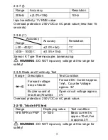
6. Do not input more than 250V DC or AC peak value to avoid 

damaging the instrument. 

 
9. .Diode and Continuity Test 

1. Insert the black lead into “COM” terminal, and red lead into 

“V/

/Hz” terminal (Note: the polarity of red lead is positive) 

2. Turn the knob to the “

” Range, then connect the test 

leads across the tested diode, the reading is the 
approximation of the diode forward voltage drop. 

3. Connect the test leads to the two points of the tested circuit, 

if the value of resistance between the two points is less 
than (70±20)

, the buzzer inside sounds 

 
10. Temperature Measurement 

When measuring Temperature, input the negative pole of 
the thermocouple sensor into “COM” terminal, and positive 
pole into “mA” terminal, connect the working side of the 
thermocouple to the surface or inside of the tested subject, 
to read the Fahrenheit temperature from LCD directly. 

 
11. TRIODE hFE 

1. Set the range knob to hFE. 

2. Insert the test accessory into “

COM

” and “

mA

” terminal. 

3. Verify the type of the transistor is NPN or PNP, insert the 

emitter, basic and collector to the proper jack on test 

accessory. 


12. Data Hold


Press the HOLD key, the present data is held on LCD. 

 
13. Auto Power Off 

Stop working around 15 minutes, the instrument will auto 
off and get into the sleeping mode. 


10

Содержание MT-1270

Страница 1: ...MT 1270 3 1 2 Digital Multimeter User s Manual 1st Edition 2013 2013 Copyright by Prokit s Industries Co Ltd...

Страница 2: ...limit when measuring each range 2 The safety voltage is below 36V please make sure the test leads connect reliably link up correctly isolate properly to avoid electric shock when measuring the voltage...

Страница 3: ...Accessory user manual CAT III test leads temperature probe test socket Technical Property 2 1 Accuracy a x reading digits at 23 5 relative humidity 75 one year calibration guarantee since the time dis...

Страница 4: ...RMS of sine wave 2 3 3 DCA Range Accuracy Resolution 2mA 1uA 20mA 0 8 10d 10uA 200mA 1 2 8d 100uA 10A 2 0 5d 10mA Max input voltage drop 200mV Max input current 10A less than 10 seconds Overload prote...

Страница 5: ...ad protection 250V DC and AC peak value Note At Range 200 short circuit the test lead to test the wire resistance and then subtract it from the real measurement WARNING DO NOT input any voltage at res...

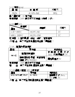
Страница 6: ...any voltage at this range for safety 2 3 9 Diode and Continuity Test Range Description Test Condition Forward voltage drop of diode Forward DC Current approx 1mA Counter Voltage approx 3V Buzzer soun...

Страница 7: ...ing terminal 6 Voltage Resistance and diode Continuity Frequency measuring terminal 7 In common terminal Capacitance Temperature HFE Frequency measuring terminal 8 Power switch Power on off 9 Backligh...

Страница 8: ...erminal and red lead into mA terminal Max 200mA or red lead into 10A terminal Max 10A 2 Tern the knob to the DCA Range then connect the test leads into the tested circuit in series the tested current...

Страница 9: ...measuring 10A note it will affect the accuracy of measurement and damage the instrument to continuously measure large current to make the circuit heat 6 Resistance Measurement 1 Insert the black lead...

Страница 10: ...reading on LCD will gradually approach zero please ignore it it doesn t affect the accuracy of measurement 5 When severe creepage or capacitor breakdown measured at large capacitance range LCD will di...

Страница 11: ...han 70 20 the buzzer inside sounds 10 Temperature Measurement When measuring Temperature input the negative pole of the thermocouple sensor into COM terminal and positive pole into mA terminal connect...

Страница 12: ...do not use the strong solvent like the abrasive cleaner and alcohol etc 4 Take out the battery if not use the instrument for a long time to prevent the battery leaking and the liquid to corrode the i...

Страница 13: ...lace battery symbol appearance Replace battery No current input Replace fuse Error value Replace battery 1 The user manual is subject to change without notice 2 The contents in the user s manual are c...

Страница 14: ...MT 1270 3 1 2 26mm LCD A D 1 IEC1010 2 36V 36V 25V 3 4 5 6 7 8 13...

Страница 15: ...2 1 3 A D 1 4 3 1 5 1 1 1 6 1 7 0 40 80 1 8 9V NEDA1604 6F22 1 9 182 x 90 x 46 1 10 320 g 9V 1 11 CATIII 2 2 1 a 23 5 75 2 2 2 3 1 DCV 200mV 100uV 2V 1mV 20V 10mV 200V 0 5 3d 100mV 1000V 0 8 10d 1V 1...

Страница 16: ...0mV 750V 1 2 10d 1V 10M 1000V 20V 40 200 Hz 200V 750V 40 100 Hz 2 3 3 DCA 2mA 1uA 20mA 0 8 10d 10uA 200mA 1 2 8d 100uA 10A 2 0 5d 10mA 200mV 10A 10 0 2A 250V 10A 250V 2 3 4 ACA 20mA 1 0 15d 10uA 200mA...

Страница 17: ...V 40 200 Hz 2 3 5 200 0 8 5d 0 1 2k 1 20k 10 200k 100 2M 0 8 3d 1k 20M 1 0 25d 10k 200M 5 0 30d 100k 0 7V 250V 200 2 3 6 C 36V 2nF 2 5 20d 1 pF 20nF 2 5 20d 10pF 200nF 2 5 20d 100pF 2uF 2 5 20d 1nF 20...

Страница 18: ...2 3 7 freq 20kHz 3 0 18d 10Hz 1V 250V 15 2 3 8 20 400 1 0 5d 1 400 1000 1 5 15d 1 K 2 3 9 1mA 3V 70 20 3V 250V 2 3 10 hFE hFE NPN PNP 0 1000 10uA Vce 3V 17...

Страница 19: ...1 2 HOLD Hold Hold 3 4 200mA 5 10A 6 7 8 POWER 9 10 LED 1 COM V Hz 2 DCV 1 2 1 1 COM V Hz 2 ACV 18...

Страница 20: ...19 1 2 1 1 COM mA 200mA 10A 10A 2 DCA 1 2 1 3 200mA 10A 10A 1 COM mA 200mA 10A 10A 2 ACA 1 2 1 3 200mA 10A 10A...

Страница 21: ...20 1 COM V Hz 2 1 1 1M 2 3 1 mA COM 2 1 2 1 3 4 5 6 1uF 1000nF 1nF 1000pF...

Страница 22: ...1 COM V Hz 2 1 10Vrms 2 3 4 250V 1 COM V Hz 2 3 70 20 COM mA hFE 1 hFE 2 COM mA 3 NPN PNP 15 POWER 21...

Страница 23: ...1 2 3 4 4 1 9V LCD 4 1 1 4 1 2 9V 9V 4 1 3 22...

Страница 24: ...23...

Отзывы: