


5099N Series User Manual
92
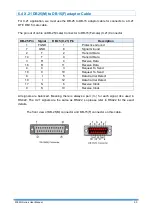
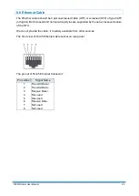
6.5 Console Cable
The front view of RJ-45 console cable socket on rear panel:
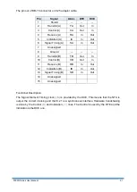
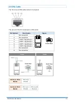
The wire connection of console cable DB-9(Female) to RJ-45:
DCD
1
RXD
2
TXD
3
DTR
4
GND
5
DSR
6
RTS
7
CTS
8
DSR
1
DCD
2
DTR
3
GND
4
RXD
5
TXD
6
CTS
7
RTS
8
NC
9
DB9 (Female)
RJ-45
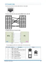
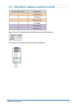
The signal direction of console cable:
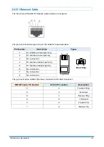
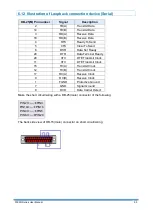
The pin assignment of RJ-45 modular jack on the console cable:
Pin Number Abbrev.
Description
Figure
1
DSR DCE ready
1 8
1 8
Top View
Front View
2
DCD Received Line Signal Detector
3
DTR DTE ready
4
GND Signal Ground
5
RXD Received Data
6
TXD Transmitted Data
7
CTS Clear to Send
8
RTS Request to Send
Содержание 5099N Series
Страница 1: ...5099N Series G SHDSL bis NTU User Manual V1 00 ...
Страница 18: ...5099N Series User Manual 15 For more detail on these sub menus please refer to following ...
Страница 21: ...5099N Series User Manual 18 3 4 1 Show Statistic on E1 Interface ...
Страница 28: ...5099N Series User Manual 25 3 5 4 Sub Menu tree for SETUP SERIAL Interface SYSTEM SETUP SETUP SERIAL ...
Страница 33: ...5099N Series User Manual 30 ...
Страница 34: ...5099N Series User Manual 31 ...
Страница 41: ...5099N Series User Manual 38 Menu tree The item according to which interface modes you have setup ...
Страница 43: ...5099N Series User Manual 40 5 4 1 Configure NTU Interface Setup Interface ...
Страница 78: ...5099N Series User Manual 75 For Serial interface mode ...
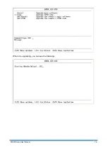
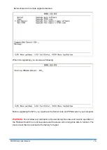
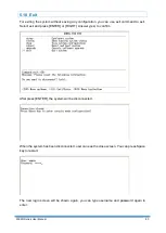
Страница 81: ...5099N Series User Manual 78 When it is upgrading you can see the following ...


