1.
When changing the diaphragm, unscrew the diaphragm rup‐
ture sensor from the dosing head.
2.
Check for electrical continuity:
3.
Using a blunt insulating probe (Ø 2 ... 3 mm, no sharp
edges), press into the channel of the diaphragm rupture
sensor.
ð
Check that there is no electrical continuity
4.
Release the pin again.
ð
Electrical continuity must be re-established.
5.
Repeat the test several times.
6.
If everything is working correctly, screw the diaphragm rup‐
ture sensor into the dosing head with a new seal (1).
7.
If not, go to the next section.
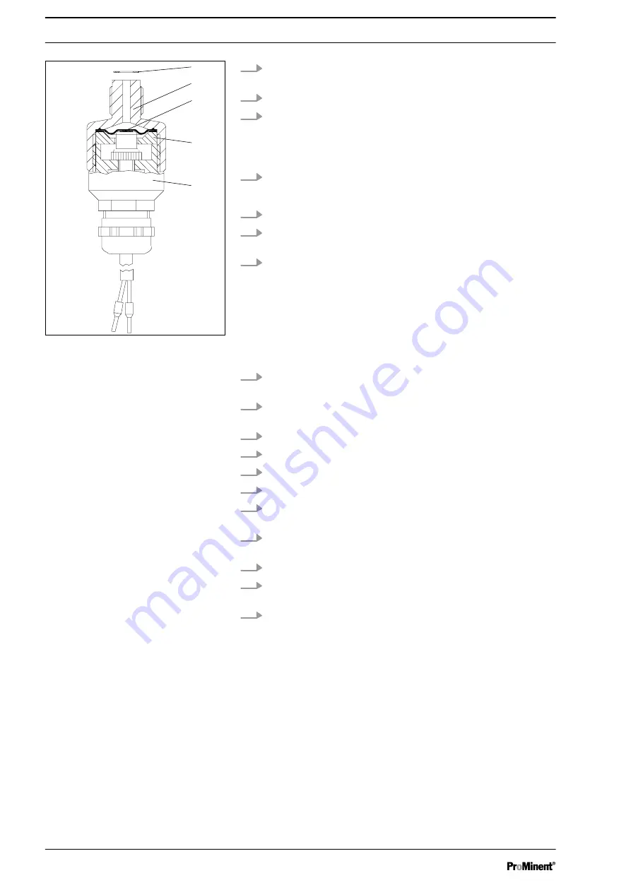
Replace separating diaphragm of the diaphragm rupture sensor
1.
Disconnect the diaphragm rupture sensor from the power
supply.
2.
When changing the diaphragm, unscrew the diaphragm rup‐
ture sensor from the dosing head.
3.
Grasp the upper section (2) of the diaphragm rupture sensor.
4.
Hold the body (5) in place with an open-ended spanner.
5.
Unscrew the top of the diaphragm rupture sensor.
6.
Clean the soiled parts.
7.
Lay the new separating diaphragm (3) with the light side
(PTFE) down into the upper section (2).
8.
Lay the plate (4) with the uneven side down into the upper
section (2).
9.
Screw the body (5) into the upper section and screw tighten.
10. Check the diaphragm rupture sensor as described in “Check
diaphragm rupture sensor".
11. If the diaphragm rupture sensor does not operate clearly and
reliably, then a new diaphragm rupture sensor must be used
without fail.
1
2
3
4
5
Fig. 20
Repairs
62
Содержание Makro TZ
Страница 45: ...Install the other units in line with their documentation Other units Installation 45...
Страница 99: ...99...


