background image

DT-511 

QUICK CONFIGURATION GUIDE


3 DT-511 CONFIGURATION 

The 

DT-511

 module is controlled and configured by means of a 

computer directly connected to the 

NMS

 web port or through an Ethernet 

network. 

3.1 Login 

The default IP of this device is 192.168.29.5. 

To connect to the module, the IP address of the computer has to be 

changed in order to have the same IP range of the module. 

If, as a example, the PC IP address is 192.168.99.252, it would be 

changed to 192.168.29.xxx (xxx can be 0 to 255 except 5 to avoid conflict 
with module IP address), then we need to use web browser to connect the 
device with our PC. 

When communication is established, the user can change the IP 

address of the module to suit the range of the Ethernet network or PC. Write 
down the new IP address if you change the default IP address of the module, 
as it is required each time you want to communicate. If after changing, you 
do not know the IP of the module, you can use a network analyser software 
like "Wireshark" (freeshare) to find out the IP. 

Check the computer IP is not the same that the module IP to avoid 

conflicts between IPs. 

Then connect the PC and the device with a net cable, and use a ping 

command to confirm they are on the same network segment and 
communication between them can be established. 

Once the communication is checked, open a web browser on the PC, 

enter the module IP and press 

ENTER

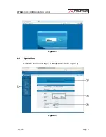
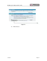
When we connect the device, it will display Login screen (figure 2). 

Enter the Username and Password (both the default Username and Password 
are “admin”) then click on ‘Login’ to start the device setting. 

Page 6 

12/2012 

Содержание DT-511

Страница 1: ...DT 511 HDMI TO DVB T MODULATOR QUICK CONFIGURATION GUIDE 0 DG0104...

Страница 2: ...IP and DVB T outputs Because of its excellent enconding performance bandwidth efficiency and moderate price it is an ideal solution to add High Definition to your programme roaster Applications includ...

Страница 3: ...4 1 8 1 16 1 32 FEC 1 2 2 3 3 4 5 6 7 8 MER 42 dB RF frequency 30 960 MHz 1 kHz step RF output level 26 10 dBm 81 97 dB V 0 1 dB step Configuration Through web server Parameters TSID VPID APID SID Net...

Страница 4: ...1 x 0 MI1962 Instruction Manual 1 x 0 DG0104 Quick configuration guide Minimal configuration needed 1 x DT 800 Power and Control Module 1 x DT 900 Sub rack framework to install in a rack or on a wall...

Страница 5: ...33 V AC rms are dangerous Use this instrument under the specified environmental conditions The user is not allowed to perform changes inside the equipment Any change on the equipment must be done excl...

Страница 6: ...e plastics used in the construction of the cover The cover should be cleaned by means of a light solution of detergent and water applied with a soft cloth Dry thoroughly before using the system again...

Страница 7: ...suit the range of the Ethernet network or PC Write down the new IP address if you change the default IP address of the module as it is required each time you want to communicate If after changing you...

Страница 8: ...DT 511 QUICK CONFIGURATION GUIDE Figure 2 3 2 Operation When we confirm the login it displays the screen figure 3 Figure 3 12 2012 Page 7...

Страница 9: ...and displays the signal source interface and real time encoding bit rate of corresponding input channel 4 TS indicator Green light indicates the TS is normal which otherwise turns to red Input 1 2 Fro...

Страница 10: ...ton to apply the default setting of Input 1 Apply Click this button to apply the modified parameters Same like Input 1 when we click on Input 2 it will display another HDMI programs input information...

Страница 11: ...right box to output Here user can select the programs which we want to output or we can output all the programs Cancel Program Similarly user can cancel the multiplexed programs from the right box All...

Страница 12: ...the programs Figure 7 Here by clicking on Add users can set the program LCN in its respective field After setting all the data users need to click on Save to save the setting After setting all the dat...

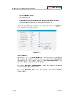
Страница 13: ...e need After setting the parameter we need to click on Apply to save the setting Figure 9 Modulator Setting When entering in Modulator it will display the Modulator Configuration screen figure 10 Here...

Страница 14: ...dulator parameters Figure 10 Save Restore When user clicks on Save Restore from the menu it will display the screen as figure 11 Here user can save the configuration permanently to the device Click on...

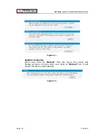
Страница 15: ...ATION GUIDE Figure 11 Restart the Device When user clicks on Reboot from the menu the screen will display as figure 12 Here when user clicks on Reboot box it will restart the device automatically Figu...

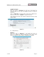
Страница 16: ...d the path of the device update file for this device then click on Update to update the device After updating the device user needs to restart the device by using Reboot option Figure 13 1 Browse Butt...

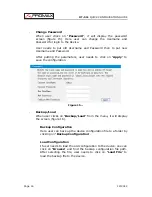
Страница 17: ...ick on Apply to save the configuration Figure 15 Backup Load When user clicks on Backup Load from the menu it will display the screen figure 16 Backup Configuration Here user can back up the device co...

Страница 18: ...DT 511 QUICK CONFIGURATION GUIDE Figure 16 1 Browse Button 12 2012 Page 17...

Отзывы: