I n s t a l l a t i o n G u i d e l i n e s
10
9
INSTALLATION CONTINUED
7
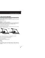
. Strip approximately 3/8 inch off the insulation of the cable.
8
. Run the AC cable through the clamp and into the wiring box.
9
. Using a screwdriver, loosen the wire attachment screws on the terminals by
about five turns.
10
. Insert and fasten the Ground wire into the corresponding terminal.
11
. Insert and fasten the Line and Neutral wires into the corresponding terminals.
12
. Tighten the Strain Relief screws, leaving some slack inside the output wiring box.
Note: If using standard wire it is recommended that you use proper crimp terminal connectors.
Chassis Ground Connection
Using a length of wire no smaller than one size smaller than the DC power cables. Connect
one end of this cable to the DC grounding connector at the inverter and the other end to
the vehicle chassis or bending system
I n s t a l l a t i o n G u i d e l i n e s
PERFORMING CHECKS PRIOR TO INSTALLATION
Before starting up your inverter, ensure these conditions are met:
- Verify the chassis ground is properly installed.
- Verify the On/Off switch is in the Off position.
- Verify the Positive (+) battery cable is connected to the positive (+) battery terminal.
- Verify the Negative (-) battery cable is connected to the negative (-) battery terminal.
- Verify the battery voltage is within the proper range for this unit (10.5-15.3 volts DC).
- Verify the DC fuse is intact.
PERFORMING CHECKS PRIOR TO INVERTER START-UP
When you are ready to test your installation and operate the TruePower400PS Inverter,
close the DC fuse and disconnect or the DC circuit breaker to supply DC power to the
TruePower400PS inverter.
Display Functions of the On/Standby Switch and Light Pattern:
The ON/OFF switch turns the TruePower400PS inverter to ON or to OFF:
- In the On position, the Inverter Fault LED light illuminates Green. The TruePower400PS
begins inverting and provides 400 watts of sine wave power, if shore power is not present.
- In the Off position with no shorepower present, the TruePower400PS Inverter draws
no current from the battery. None of the front panel LED lights are illuminated.
- In the Off position, with the AC input cord plugged into shorepower, the Green AC Input
light illuminates and the appliances connected to the TruePower400PS can be operated.
INSTALLATION CONTINUED
To test the TruePower400PS Inverter:
1. Turn the On/Off switch to the ON position. The Inverter/Fault LED light illuminates Green.
2. Plug an appliance of 400 watts or less into the AC outlet.
3. Turn the appliance ON to verify that it operates.
4. If the Inverter/Fault light illuminates Red, see the TruePower400PS Inverter
“Troubleshooting” section.
Shorepower Mode
: When the shorepower source is connected, the TruePower400PS
inverter transfers the appliances to the shorepower source and goes directly into
shorepower mode. The AC Input LED light illuminates Green. The inverter will transfer
power with the ON/Off switch in either the ON or Off position.
Inverter Mode
: If the ON/Off switch is in the ON position, the TruePower400PS will
automatically supply the appliance(s) with the inverter power if the shorepower source
fails or becomes disconnected.
INSTALLING YOUR REMOTE CONTROL
1.
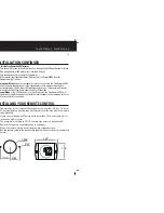
Find a location for the remote with enough area to mount the 1-3/4" by 2-1/4" panel.
2.
Using tape (painters masking tape is preferred) cover the area where the remote
is to be mounted.
3.
Create a center drill point. Measure out to both sides 31/32' and create a drill
point on each side of center.
4.
The center hole is drilled to 1-5/16". The two side holes are drilled to 3/32".
5.
Remove the tape and sand smooth any rough edges.
6.
Mount the remote into the panel using the two supplied screws.
7.
Run the remote cable to the inverter and plug the connector into the jack labeled
"Remote"
31/32"
31/32"
1-5/16"
3/32"
2.25"
1.75"
Содержание 79400
Страница 3: ......


