


9
8
I n s t a l l a t i o n
I n s t a l l a t i o n
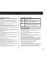
DC Wiring Diagrams
12 Volt 40 Amp Length Out and Back
Wire length 10' 15' 20' 25' 30'
AWG 8 6 6 4 4
12 Volt 50 Amp
Wire length 10' 15' 20' 25' 30'
AWG 6 6 4 4 2
12 Volt 60 Amp
Wire length 10' 15' 20' 25' 30'
AWG 6 4 4 4 2
24 Volt 25 Amp
Wire length 10' 15' 20' 25' 30'
AWG 12 12 10 10 8
24 Volt 30 Amp
Wire length 10' 15' 20' 25' 30'
AWG 8 6 6 4 4
Three Bank Installation (FIG.1)
Battery negative wires are run separately to
the boat’s DC buss bar (not provided). Then
a single connection is made to the charger.
Two Bank Installation (FIG.2)
Same as three bank leaving one output post
without a connection.
One Bank Installation (FIG.3)
Connect to one positive post and use two
jumpers to tie all positives together.
Wiring Length is round trip
Note: Circuit Protection should be attached
to each positive charger lead 7 inches from
the battery or the battery connection point
(ABOVE) It is recommended that a jumper(s) be used between unused positive output post(s)
and a used post connected to a battery. Please note you can connect all three positive posts
together to form a single bank connection.
All DC wire terminations and connections must be made in compliance with ABYC E-11 & A-31
bank 1
bank 2
bank 3
ProNautic
AC Input
Common
Negative
DC Outputs
ProNautic
AC Input
Common
Negative
DC Outputs
bank 1
bank 2
ProNautic
AC Input
DC Outputs
Common
Negative
bank 1
Indicates Jumper Wire
FIG.1
FIG.2
FIG.3
Indicates a Fuse
Note:
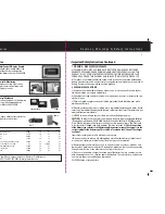
Installation
1)
Make sure to mount the charger in a
DRY
ventilated location with easy access. Remember
to leave plenty of room for battery cables and AC wiring.
2)
Six inches of clearance is required on all sides. (Including the front/ face)
3)
Use the ProNautic as a template for drilling four 1/8” pilot holes if using stainless steel
sheet metal screws (1/4 x 1-1/4” is recommended) or drill four 1/4” through holes if using
1/4” through-bolts with washers, lock washers and lock nuts.
Note: Charger dimensions are in millimeters nominal measurement
4)
Battery cables, connections and installation must comply with ABYC E-11 standards.
We recommend that each ungrounded DC conductor (Positive cable) be provided with
an over current protection fuse within 7 inches of connection to the battery or battery
connection point. The fuse rating should be at least 10 amps higher than the rated full
output of the charger. See ABYC E-11 for specific requirements. Over current protection
within 7 inches of the charger is not required as the ProNautic is self limiting and can not
exceed its rated current output. The internal fuses protect the unit against reverse polarity.
159mm (6-1/4”)
1240, 1250, 2425: 383mm (15-1/16”)
1260, 2430 : 426mm (16-3/4”)
209mm (8-1/4”)
1240, 1250, 2425: 432mm (17”)
1260, 2430 : 476mm (18-3/4”)
ø6.5mm (ø1/4”)


