7
Selecting a Charging Profile & Understanding Battery Types
10
I n s t a l l a t i o n
Charging Information
Note: Before energizing the charger, please select the appropriate battery type determined
by the rotary switch position (shown below). You will find charging profiles and
recommendations on page 6 of this manual. Should you have questions about which
charging profile is right for your batteries please contact the battery manufacturer.
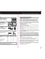
Rotary Switch
Temp Sensor
Reverse Polarity Fuses
Positive Battery Terminals
Negative Terminal
AC Connections
5)
AC power should not be present until step 12 is completed
. After connecting the
AC and DC cables to the charger use cable support on the cables within 6” of the
charger for both the AC and DC cables.
6)
Be cautious when connecting battery cables to the ProNautic charger and check to make
sure AC power is off.
Be careful when placing battery cables near one another to avoid possible
shorting or arcing (sparking) that can occur when positive and negative wires touch.
7) US 120 Volt or European 230 Volt AC Connections:
(For US 240V AC please refer to
step #8). A terminal strip is provided on the charger for AC input. Connect Black (Europe-
Brown) to the connection marked Line. Connect White (Europe-Blue) to connection
marked Neutral. Connect Green (Europe-Green/Yellow) to connection marked (Ground/
Earth). Install an appropriate circuit breaker dedicated to the charger at the boat’s
electrical panel. Please refer to page 11 for proper fusing ratings.
8)
US 240 Volt AC Connections:
(If using 120 volt AC or European 230 volt AC please
refer to step #7 and ignore this step). A terminal strip is provided on the charger for
AC input. Connect Black to the connection marked Line. Connect Red to connection
marked Neutral. Connect Green to connection marked (Ground/ Earth). Install an
appropriate circuit breaker dedicated to the charger at the boat’s electrical panel.
Please refer to page 11 for proper fusing ratings.
Please note: All AC wire connections and installations must be made in compliance
with ABYC E-11.
Minimum AC wire size 105˚c C wire - #14 up to 15 amp - #12 up to 20 amp. See ABYC E-11 for
exact wire sizes for length of run, ampacity, temperature, location and number of wires in bundles.
Shown left is the ProNautic AC power strip.
Before removing cover make sure shore
power is disconnected. All connections
should be tight, check to make sure that
no wires are severed or broken
Shown left is the AC terminal block that is
shown in the above photo. Please note
the connections and wire appropriately.
The circuit board is also labeled to indicate
where connections go.
GROUND
LINE
NEUTRAL
AC Input
AC Cable
Strain Relief


