


6
Selecting a Charging Profile & Understanding Battery Types
11
I n s t a l l a t i o n
AC Connections Continued
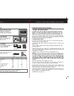
Drip Shield Installation
11)
Install the provided drip shield to prevent
potential water damage. ProMariner recommends
mounting the drip shield using #10 x 3/4” Stainless
Steel sheet metal screws.
Please note water damage is not covered
by warranty.
Applying AC Power
12)
Apply AC power, after approximately 6 seconds the LEDs will illuminate. Battery type
LED will be lit to indicate battery type selected. The Fast Charge and Absorption Charge
LEDs will both initially illuminate and after 5 minutes the Absorption LED will extinguish.
This is a hold function to keep the charger from going to Absorption in the case of a totally
dead high resistance battery. None of the Fault LEDs should illuminate, it is possible that
the Under Voltage yellow LED will be on if the batteries are in a deeply discharged condition.
This LED will extinguish as the batteries charge in up to 3 to 4 hours depending upon the
capacity of the battery banks. The charger modes are as follows Fast Charge, Absorption,
Float and Reconditioning.
Should you have any questions please visit www.promariner.com or call 1-800-824-0524.
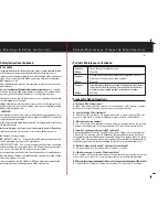
DC Grounding
Connection
DC Grounding Connection
9)
The case DC grounding connection should be
connected to the boats DC engine negative buss
terminal using a cable one size smaller than the
negative battery cable.
10)
After all cables are in place recheck
connections making sure all connections are
tight, confirm the charger is in a dry location.
Charger Model
110 volt breaker
220 volt breaker
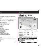
ProNautic 1240
13 Amp
7 Amp
ProNautic 1250
16 Amp
8 Amp
ProNautic 1260
18 Amp
9 Amp
ProNautic 2425
15 Amp
8 Amp
ProNautic 2430
20 Amp
10 Amp
Recommended
AC Breaker Size
Drip Shield
ProNautic
1/2”
Setup and Operation Continued
accessory damage is high. Next remove the end cap located on the DC side of the charger. With
the AC power off, change the rotary switch to position 8. After the adjustment replace the DC
cover and turn the charger on. The charger will go into a Flooded Lead Acid charge cycle followed
by the desulfation mode for 4 hours and then shut off. After this is complete turn off AC power.
Remove the DC terminal end cap and reset the rotary switch back into the original setting, reinstall
the DC cover and turn on the AC power. Charger will now be in normal operating mode.
Note: The charger is equipped with an internal temperature sensor that will shutdown
the charger if internal temperature reaches unsafe levels.
Note: Your ProNautic charger is equipped with a fan, which is temperature controlled
and will only run when cooling is necessary.
The charger is self limiting, reverse polarity and ignition protected. If at any time you have
trouble configuring the charger or need technical information visit www.promariner.com,
call ProMariner at 1-800-824-0524 or email [email protected].
Selecting a Charging Profile and Understanding Battery Types
Charging System Factory Charge Profile Setting
There are three primary types of batteries; Flooded (Lead Acid), AGM (Absorbed Glass
Mat) and GEL Cell (Gelled Electrolyte Lead-Acid). Traditionally, the most common type of
batteries used are Flooded (Lead Acid batteries).
***If you are unsure as to what kind of battery you have, we recommend that you contact
the manufacturer of the battery.
Profiles shown above are only recommendations please contact Manufacturer of
batteries if you have any questions.
NOTE: AGM (Absorbed Glass Mat) batteries are not GEL (Gelled Electrolyte Lead-Acid)
batteries. AGM batteries are charged at different charging profiles and are not the same.
Switch Setting
12 volt system
24 volt system Battery Type
Position Number 1 14.0 Absorption & 13.7 Float 28 & 27.4 GEL 1
Position Number 2 14.3 Absorption & 13.3 Float 28.6 & 26.6
AGM
Position Number 3 14.4 Absorption & 13.6 Float 28.8 & 27.2
Sealed Lead Acid
Position Number 4 14.4 Absorption & 13.8 Float 28.8 & 27.6
GEL 2
Position Number 5 14.6 Absorption & 13.7 Float 29.2 & 27.4 AGM 2
Position Number 6 14.8 Absorption & 13.3 Float 29.6 & 26.6
Flooded
Position Number 7 15.1 Absorption & 13.6 Float 30.2 & 27.2 Calcium
Position Number 8 15.5 Volts for Desulfation Mode 31.0 Desulfation Desulfation
Rotary Switch Settings


