16
10.7
Thread cutting
Threading is performed in multiple passes with a threading
tool.
Each depth of cut should be about 0,2mm and become less for
the finishing passes.
A) To cut inch and metric threads
Set the machine up for the desired threading pitch (see
chapter 8.2).
Select the lowest possible spindle speed.
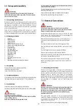
Engage the halve nut (CC, Fig 10‐6).
NOTE:
The halve nut must stay engaged during the entire
threading process.
‐ Set the tool up for the threading pass.
‐ Start the motor.
‐ When the tool approaches the end of cut, stop the motor and
at the same time back the tool out, so that it clears the thread
diameter.
‐ Start the motor in reverse direction, let the cutting tool travel
back to the starting point.
Repeat these steps until you have obtained the desired results.
B) To cut metric threads with pitch 0,4/ 0,5/1,0/2,0 mm:
The halve nut can be opened at the end of cut, rather than the
motor being stopped and reversed.
10.8
Drilling operation
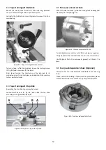
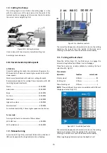
Use a drill chuck with MT2 arbor (option) to clamp centre drills
and twisted drills in the tailstock (Fig 10‐8).
Figure 10‐8: Drilling operation
For recommended speeds refer to section 10.4
To eject the drill chuck, fully retract the tailstock quill.
11.0
User‐Maintenance
WARNING:
Before any intervention on the machine, disconnect it from
electrical supply, pull the mains plug. Failure to comply may
cause serious injury.
An important security factor is the cleaning of the machine, of
bed, carriage and slides, of the floor and the surrounding
places.
Loose objects could come into contact with the moving chuck
or workpiece, creating hazards.
Empty the chip tray regularly.
Replace the coolant regularly, follow manufacturer’s advice.
Check that bolts are tight and electrical cords are in good
condition. If an electrical cord is worn, cut, or damaged in any
way, have it replaced immediately.
11.1
Lubrication
Spindle bearings are pre‐lubricated and sealed, and require no
further lubrication.
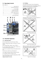
Weekly apply oil:
DIN 51502 CG ISO VG 68
(e.g. BP Maccurat 68, Castrol Magna BD 68, Mobil Vectra 2)
1…oil balls on change gear hubs
2…oil bed ways lightly
3…oil tailstock quill over entire length
4…oil lead screw on entire length
5…oil ball on lead screw bracket
6…oil balls on top slide
7…oil balls on tailstock
8...oil balls on carriage
9...oil balls on apron
Monthly apply grease:
DIN 51807-1 non slinging grease
(e.g. BP L2, Mobilgrease Special).
10…grease teeth of change gears
11…grease rack over entire length
Gear box oil:
DIN 51517‐2 CL ISO VG 68
(e.g. BP Energol HLP 68, Mobil DTE Oil Heavy Medium)
Oil must be up to indicator mark in oil sight glass.
In case, fill up with oil by removing plug on right side of gear
box.
Содержание PBD-2555V
Страница 18: ...18 15 0 Replacement Parts PBD 2555V Assembly Breakdown 1...
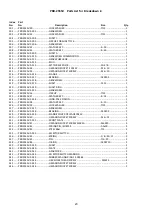
Страница 20: ...20 PBD 2555V Assembly Breakdown 2...
Страница 22: ...22 PBD 2555V Assembly Breakdown 3...
Страница 24: ...24 PBD 2555V Assembly Breakdown 4...
Страница 26: ...26 PBD 2555V Assembly Breakdown 5...
Страница 28: ...28 PBD 2555V Assembly Breakdown 6...
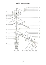
Страница 30: ...30 PBD 2555V Assembly Breakdown 7...
Страница 32: ...32 PBD 2555V Assembly Breakdown 8...
Страница 34: ...34 16 0 Wiring Diagrams PBD 2555V 1 230V PE 50Hz...

