background image


12A 


2.


Connect   the   units   together   in   a   `daisy   chain`   by   using   the   XLR   plug   from   the   output   of   one   unit   

to   the   input   of   the   next   unit.   The   cable   can   not   branched   or   split   to   a   `Y`   cable.   DMX   512   is   a   

very    high-­‐speed    signal.    Inadequate    or    damaged    cables,    badly    soldered    joints    or    corroded   

connectors   can   easily   distort   the   signal   and   even   shut   down   the   system.   

3.


The   DMX   output   and   input   connectors   are   of   pass-­‐through   type   to   maintain   the   DMX   circuit,   

when   one   of   the   units’   power   is   disconnected.   

4.


Each   unit   needs   to   have   an   address   set   to   receive   the   data   sent   by   the   controller.   The   address   

number   is   between   0-­‐511   (usually   0   &   1   are   equal   to   1).   

5.


The   end   of   the   DMX   512   system   should   be   terminated   to   reduce   signal   errors.   

6.


3   pin   XLR   connectors   are   more   popular   than   5   pin   XLR.   

3   pin   XLR:   Pin   1:   GND,   Pin   2:   Negative   signal   (-­‐),   Pin   3:   Positive   signal   (+)       

5   pin   XLR:   Pin   1:   GND,   Pin   2:   Negative   signal   (-­‐),   Pin   3:   Positive   signal   (+)   

Pin   4/Pin   5:   Not   used.   


4.2   Address   Setting       

If   you   use   a   universal   DMX   controller   to   control   the   units,   you   have   to   set   DMX   address   from   1   to   

512   so   that   the   units   can   receive   the   DMX   signal.   

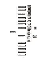
Press   the   

MENU

   button   to   enter   menu   mode,   select


the


DMX   Address

,   press   the   

ENTER

   button   to   

confirm,   the   present   address   will   blink   on   the   display,   use   the   

UP

   and   

DOWN

   button   to   adjust   the   

address   from   001   to   512,   press   the   

ENTER   

button   to   save.   Press   the   

MENU

   button   to   return   back   

to   the   last   menu   or   leave   the   unit   idle   for   7   seconds   to   exit   the   menu   mode.   

Please   refer   to   the   following   diagram   to   address   your   DMX512   channel   for   the   first   4   units


Channel   mode   

Unit   1   

Address   

Unit   2   

Address   

Unit   3   

Address   

Unit   4   

Address   

8   channels   

1   

9   

17   

25   

14   channels   

1   

15   

29   

43   


Содержание Kudos 200ZS

Страница 1: ...Kudos 200ZS Order code ELUM038 User Manual www prolight co uk...

Страница 2: ...al Specifications 4 3 How To Set The Unit 4 3 1 Control panel 4 3 2 Main Function 6 4 Control By Universal DMX Controller 11 4 1 DMX 512 Connection 11 4 2 Address Setting 12 4 3 DMX 512 Configuration...

Страница 3: ...ease disconnect main power before replacement or servicing Please make sure there are no flammable materials close to the unit while operating as it is fire hazard Please use a safety cable when fixin...

Страница 4: ...dealer Installation The unit should be mounted via its screw holes on the bracket Always ensure that the unit is firmly fixed to avoid vibration and slipping while operating Make sure that the struct...

Страница 5: ...ing 0 100 Color macro effect Blue LCD display for easy navigation Ideal for stage theatre TV studio rental and discotheques Input Voltage AC 100V 240V 50 60Hz Power Consumption 198W LED Sources OSRAM...

Страница 6: ...T 6 3A Protects the unit from electrical damage 9 POWERCON IN Connect to a socket AC 100 240V 50 60Hz via the supplied mains cable 10 POWERCON OUT Connect to supply power to the next unit 11 DMX IN 3...

Страница 7: ...he ENTER button and the display will blink Use the DOWN and UP button to change the mode Once the required mode has been selected press the ENTER button to setup To go back to the functions without an...

Страница 8: ...7A...

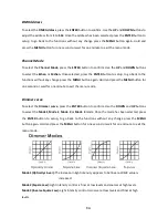
Страница 9: ...press the MENU button again Hold and press the MENU button for one second or wait for one minute to exit the menu mode Dimmer curve To select the Dimmer curve press the ENTER button to confirm Use th...

Страница 10: ...to go back to the functions without any change press the MENU button again Hold and press the MENU button for one second or wait for one minute to exit the menu mode Back Light To select the Back Ligh...

Страница 11: ...he ENTER button and the unit will run a self test using its built in programs To go back to the functions press the MENU button again Hold and press the MENU button for one second or wait for one minu...

Страница 12: ...e ENTER button and all channels of the unit will return to their standard position 4 Control By Universal DMX Controller 4 1 DMX 512 Connection 1 The last unit in the DMX chain has to be terminated wi...

Страница 13: ...connectors are more popular than 5 pin XLR 3 pin XLR Pin 1 GND Pin 2 Negative signal Pin 3 Positive signal 5 pin XLR Pin 1 GND Pin 2 Negative signal Pin 3 Positive signal Pin 4 Pin 5 Not used 4 2 Add...

Страница 14: ...13A 4 3 DMX 512 Configuration 8 Channels Mode...

Страница 15: ...14A 14 Channels Mode...

Страница 16: ...see if linked properly 2 If the DMX LED is on but no response from the channels check the address settings and DMX polarity 3 If you have intermittent DMX signal problems check the cables or connecto...

Страница 17: ...equency depends on the environment in which the fixture operates damp smoky or particularly dirty surrounding can cause greater accumulation of dirt on the unit s optics Clean with soft cloth using no...

Страница 18: ...17A...

Страница 19: ...th the provision of the Electromagnetic Compatibility EMC Directive 89 336 EEC EN55103 1 2009 EN55103 2 2009 EN62471 2008 EN61000 3 2 2006 A1 2009 A2 2009 EN61000 3 3 2008 Harmonized Standard EN 60598...

Страница 20: ...19A Innovation Quality Performance...

Отзывы: