Prodigy
r
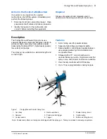
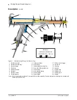
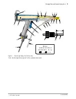
Manual Powder Spray Gun
7
Part 1053680E05
E
2007 Nordson Corporation
Installation
(contd)
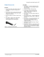
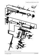
6. Push the delivery tubing into the adapter (20)
until it bottoms out against the powder tube
(21). Thread the lock knob into the adapter and
finger-tighten it until snug.
7. Route the delivery tubing to the appropriate
powder pump. Remove the outlet fitting (rear
fitting) and O-ring and install them on the
tubing, then screw the fitting back onto the
pump.
8. Connect suction tubing as described in the
powder pump manual or Color-on-Demand
installation manual.
9. Use cable ties or spiral-cut tube wrap to bundle
together the gun control cable, pattern air
tubing, and powder tubing.
ATEX Special Condition For Safe Use:
This applicator shall only be used with the Prodigy
Manual Controller.
Operation
WARNING: This equipment can be
dangerous unless it is used in
accordance with the rules laid down in
this manual.
All gun functions are set and controlled by the
manual gun controller.
Presets
A preset is a group of spray settings. The gun
controller provides 10 presets. Use the presets to
save optimal spray settings for parts with different
features.
Gun ON LED
The LED on the end plate lights when the spray
trigger is pulled and high voltage is generated.
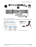
Pattern Control Trigger
The pattern control trigger toggles between the
preset settings (High mode) and the Low mode
settings. Use it to change the pattern air and
powder flow as needed when part features change.
When in Low mode, a down-pointing arrow (
⇓
) is
appears to the right of the gun icon.
NOTE: If you change presets while spraying in
Low mode, the controller immediately switches to
High mode, spraying with the new preset settings.
Maintenance
WARNING: Inspection and maintenance
of this equipment in Europe shall carried
out by suitably trained personnel in
accordance with the applicable code of
practice. EN60079-17
Daily: Blow off the gun exterior with low-pressure
compressed air and wipe it clean with a soft cloth.
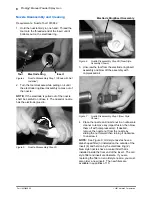
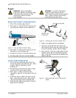
Weekly: Manually perform a hard purge, then
remove the retaining nut, nozzle, and powder tube.
Inspect the powder tube and nozzle for wear.
Replace any worn parts.
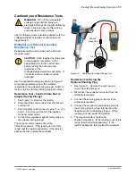
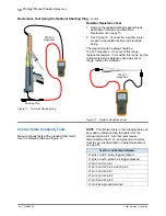
Periodically: Check the resistance of the voltage
multiplier and resistor with a megohm meter as
described in Continuity and Resistance Checks on
page 11. Replace any components that do not
meet the specifications.
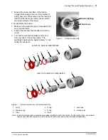
As Required: Disassemble the nozzle and clean
the internal parts. Replace any worn parts. Refer
to Nozzle Disassembly and Cleaning on the
following page for instructions.
Содержание Powder Spray Gun
Страница 28: ...Prodigyr Manual Powder Spray Gun 26 Part 1053680E05 E 2007 Nordson Corporation...
Страница 30: ......


