5
English
Assembling the Shredder
Follow the steps below to assemble the shredder:
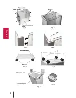
1. Assemble the box. Assemble the panels (see Fig. 1). Insert the front (transparent) panel and the
rear panel into the slots of the side panels. Pay attention to the fact that the ridges on the panels
are on the top (see Fig.2). Connect the front and rear panels to the side ones (see Fig. 3). During
assembly, please place the panels very carefully as they do not require much effort for assembly.
In the final position, the ridges’ edges of the front and the rear panels are 12mm away from the slot’s
ends in the side panels (see Fig. 4).
2. Insert the four wheels on the bottom panel. The
wheels must be placed with opposite sides of the
grooves (see Fig. 5).
3. Put the bottom panel with four wheels and the
assembled box together, and use four screws to fix it
(see Fig. 6).
4. Turn the box up side down, and let it stand on the
wheels. Set up the upper frame (make sure that the
top lath’s dowel is on the right corner, and the trans-
parent panel is facing you) (see Fig. 7), adjust the
inconsistencies by hand, and fix the frame with four
screws in the corners.
5. Set the upper unit on the waste bin so that the
transparent panel is facing you, while the upper unit’s
power cord must be on the right side (see Fig. 8).
Make sure that there are no cracks and gaps
between the waste bin and the upper unit.
Operation
1. Connect the power cord to the shredder.
2. Turn on the power switch (on the right side of the upper unit) and the power indicator light should
turn on.
3. Place one to four sheets of standard A4 format paper (density 80g/m
2
) in the feeder opening.
When there is paper in the feeder opening, the shredder will automatically turn on. After shredding
is finished, the device will turn off.
4. If the number of paper sheets exceeds the shredder’s capacity or there is a paper jam in the
feeder opening, the motor will stop and the shredder will automatically reverse and return the paper.
Remove the paper from the feeder opening and continue shredding.
5. When finished shredding, turn off the power switch.
Unloading the Waste Bin
1. Turn off the power switch.
2. Unplug the power cord from the shredder.
3. Remove the upper unit from the waste bin by the carrying handle.
4. Unload the waste bin.
5. Install the upper unit on the waste bin (Page 5).
Fig. 8
Содержание PRO KGB C-11CC
Страница 4: ...4 English Fig 1 Fig 2 Fig 3 Fig 4 Fig 5 Fig 6 Fig 7...
Страница 10: ...10 Deutsch Fig 1 Fig 2 Fig 3 Fig 4 Fig 5 Fig 6 Fig 7...
Страница 15: ...15 1 2 3 4 5 6 7 8 30 10 1 2 3 4...
Страница 16: ...16 1 2 3 4 5 6...
Страница 17: ...17 1 1 2 3 12 4 2 5 3 6 4 7 5 8 1 2 3 4 80 4 5 8...
Страница 18: ...18 1 2 3 4 5 8 1 2 2 1 4 60000 3 0 8 1 2 30 1 2 3...
Страница 19: ...19...
Страница 20: ...PRO INTELLECT TECHNOLOGY www pro intell com...


