pro-gard.com
800.480.6680
5
Passenger-side trim panel, carfully align the Template
per their included instructions. Using a 1” Hole Saw
drill the clearance holes as marked on the template.
Replacment of sound insulation is optional.
B. Replace the trim panel, insureing that the standoff’s
protrude through the panel.
XI.
Installing Partion Mounting Plate
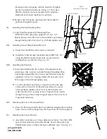
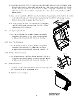
A. Attach the Passenger-side Mounting Plate
(3PRT5611-02P) using the supplied 5/16-18 x 3/4”
Button head screws (3X149) to the standoff’s protruding
through the B-pillar trim (See Fig. 9). Hand tighten only.
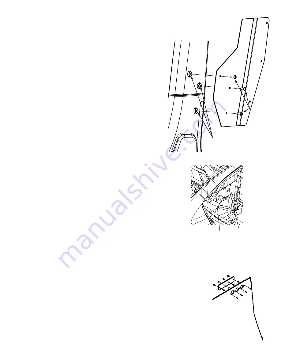
XII. Installing Center Hump Mount Bracket
A. Insure that the OEM center consle is removed.
B. Install the Center Hump Mount Bracket (3PRT5611-03)
using the OEM console mount tabs, secure with the
included Screws (3X162). (See Fig. 10)
XIII. Installing the Partition
STANDOFFS
3PRT5611-01P
3X149
B-PILLAR TRIM
A. Insert the partition into the vehicle, lift and position the
partition so that it alines with the Partition Mounting Plate,
and Center Support Bracket. Secure the Partition using the
supplied 1/4-20 x 3/4” Carriage Bolts (3X36) and 1/4-20
Whiz nuts (3X16Z) Hand tighten only.
B. Level the partition by placing a torpedo level on the hem
at the bottom front side of the partition. Raise the center
of the partition slightly above level as the brackets will
settle into the floor covering in time. Tighten the two bolts
through the top of the Center Support racket. Check for level.
Tighten all fasterners.
XIV. Installing the Lower Extension Panel
A. Place the Panel against the back side parttion alinging the mounting
holes. Secure with carriage bolts 3X36 and nuts 3X16Z four places.
XV. Installing the Center Divider.
A. Assemble vent plate over 3 large diameter air holes. Use (blk ABS)
spacers between plate and center divider. Secure using the long,
Philips head screws, black whiz nuts, and black caps. (See fig. 11)
Fig. 10
3PRT5611-03
3X162 (4)
FIG. 11
Fig. 9
PASSENGER SIDE SHOWN


