background image


31/46


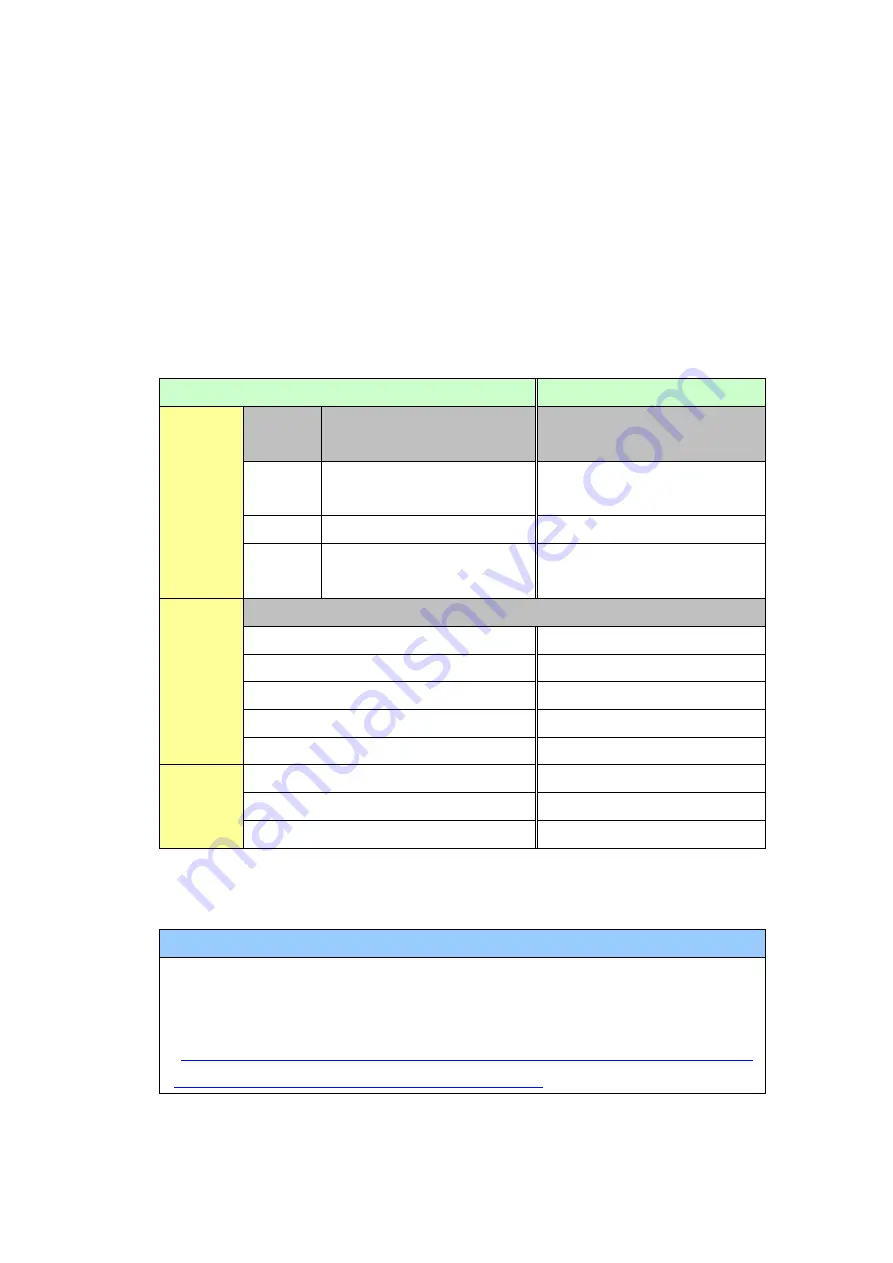
3.6.2 Differences made at the time of change to GP-4301TM 

If you change the Display Unit to GP-4301TM after data conversion from 
GP-PRO/PBIII to GP-Pro EX, the function settings GP-4301TM does not support 
are deleted from the project file. 


The functions to be deleted from the GP-Pro EX’s project files 
 

Settings on GP-PRO/PBIII 

Settings on GP-Pro EX 

Tags 

Tag 

Name 

Operation details 

Part Name 

A Tag 

Alarm Summary (Text) 
Display 

Text Alarm 

a tag 

Alarm Summary Display 

Alarm 

v tag 

Video Window Display 
Expansion Funciton 

VM Unit Display 

Parts 

Part Name 

FilingData Display 

Special Data Display 

Logging Display 

Sampling Data Display 

Data Trans Display 

Special Data Display 

CSV Display 

Special Data Display 

File Manager Display 

Special Data Display 

The 
other 
functions 

Sound Settings 

Sound Setting 

CSV Data Transfer Settings 

Transfer CSV Data on Recipe 

Data Logging Settings 

Sampling Setting 

*1


*1: 

In the Sampling settings, only the [Display/Save As CSV, Printing Language] setting that is not 

supported by GP-4301TM is deleted. 


NOTE 

For details of GP-Pro EX’s parts and functions that cannot be used or have 
restrictions on GP-4301TM, refer to [For Those Using GP-4*01TM] in the 
GP-Pro EX Reference Manual. 
(

http://www.pro-face.com/otasuke/files/manual/soft/gpproex/new/refer/me

rgedProjects/welcome/welcome_rr_gm4000.htm

)


Содержание GP-37W2

Страница 1: ...1 46 Easy Smooth GP 37W2 GP4000M Series Replacement Guidebook 3rd Edition 2014 11 Copyright 2014 11 Digital Electronics Corporation All Rights Reserved...

Страница 2: ...e Recommended Substitution GP 37W2 GP 4301TM Safety Information HAZARD OF OPERATOR INJURY OR UNINTENDED EQUIPMENT DAMAGE Before operating any of these products be sure to read all related manuals thor...

Страница 3: ...SIONS 7 2 5 EXTERNAL DIMENSIONS 8 2 6 TRANSFER CABLE 8 2 7 SERIAL INTERFACE 8 2 8 MEMORY 9 2 9 PERIPHERAL UNITS AND OPTION UNITS 9 2 9 1 BARCODE READER CONNECTION 9 2 9 2 ISOLATION UNIT 9 2 10 POWER C...

Страница 4: ...LC 32 4 1 DRIVER LIST 32 4 2 SHAPES OF COM PORTS 33 4 3 SIGNALS OF COM PORTS 34 4 4 MULTILINK CONNECTION 36 4 5 INTERNAL 2 PORT FEATURE FOR MITSUBISHI PLC 36 4 6 CABLE DIAGRAM AT THE TIME OF REPLACEME...

Страница 5: ...els Panle Cutout Dimensions mm 191 5 W x141 5 W NEW 22mm See 2 4 External Dimensions mm 207 W x157 H x58 D NEW 163 W x129 4 H x56 5 D The main module is included See 2 5 Touch Panel Type Matrix NEW An...

Страница 6: ...of connectors Connector locations on GP 37W2 and GP 4301TM are as follows GP 37W2 GP 4301TM Interface names GP 37W2 GP 4301TM 1 Power Input Terminal Block Power Connector 2 Serial I F COM1 3 Tool Con...

Страница 7: ...ors GP 37W2 has monochrome LCD but GP 4301TM has TFT Color LCD After replacement the black and white display changes to the color display When data of a monochrome model are converted to a color model...

Страница 8: ...mini B Please note that the cables GPW CB02 GPW CB03 GP430 CU02 M for GP 37W2 cannot be used for GP 4301TM 2 7 Serial interface The COM1 port on GP 4301TM is D sub 9 pin plug The COM1 port of GP 37W2...

Страница 9: ...e used However GP 4301TM allows you to connect a barcode reader on its USB interface Type A or its serial interface For the models GP 4301TM supports see OtasukePro http www pro face com otasuke qa 30...

Страница 10: ...ual 2 12 Other Notes Do not expose GP4000 series to direct sunlight Do not use GP4000 series outdoors Do not turn on GP4000 series if condensation has occurred inside the device When you are continuou...

Страница 11: ...ve GP 37W2 Installation Screen Communication Process the panel and install GP 4301TM Check the compatibility of hardware in Chapter 2 Check the connection between GP 4301TM and PLC in the GP Pro EX De...

Страница 12: ...et 1 This step is required if screen data is saved only in the GP unit not in any other device 2 The software version must be the same or higher than the version that you used when creating screen dat...

Страница 13: ...om GP 37W2 using a transfer cable GPW CB02 or GPW CB03 If you have backed up screen data this step is unnecessary skip to the next section 3 4 Convert screen data with the Project Converter 1 Connect...

Страница 14: ...14 46 3 On the Transfer window select the Setup menu and click Transfer Settings 4 In the Communication Port field select COM specify the COM port to which the cable is connected and click OK...

Страница 15: ...heck the COM port for the USB transfer cable GPW CB03 which is assigned to the PC with the Device Manager of Windows 5 Select the Transfer menu and click Receive 6 Specify the location to save the rec...

Страница 16: ...unit beforehand The Upload Information is sent to the display unit by default however you may check off the box of Upload Information to prevent screen reception by a third party You can check if the...

Страница 17: ...eceive the data 3 4 Convert screen data with the Project Converter Convert a project file prw for GP 37W2 with the GP Pro EX s Project Converter and change the model setting to GP 4301TM 1 Click the S...

Страница 18: ...ter starts up and the Project Converter dialog box opens Select Project File PRW in the Data Type 3 Click the Browse button and select a project file e g Project system A prw Click Open and the file w...

Страница 19: ...19 46 4 In Convert To designate a GP Pro EX s project file prx Click the Browse button and enter a new File Name e g Product system A prx Click Save and a new project file will be set to Convert To...

Страница 20: ...20 46 NOTE When a convert to file exists the window that confirms whether or not to overwrite the file is displayed 5 Click Convert and start the conversion...

Страница 21: ...21 46 6 If you are asked about the Convert To type as shown below select GP 4301TM on the pull down menu Click OK...

Страница 22: ...rsion If an error message is displayed during conversion refer to Project Converter Error Message http www pro face com otasuke qa gp3000 replace soft conv project_con verter_error html on our Web sit...

Страница 23: ...conversion from GP Pro PBIII for Windows are described in the saved file the project file prx after conversion can be checked and modified according to the conversion information 8 Click Close to clos...

Страница 24: ...doesn t support and the important notes see 3 6 2 Differences made at the time of change to GP 4301TM Depending on a setting of the project file the message as shown below appears the Dispay Unit may...

Страница 25: ...screen data with a USB transfer cable model ZC9USCBMB1 1 Connect your PC and GP 4301TM with a USB transfer cable model ZC9USCBMB1 If the driver of the cable has not been installed on your PC yet a di...

Страница 26: ...on the display unit After transferring a project file once this screen will not appear again 3 On the GP Pro EX s State Toolbar click the Transfer Project icon to open the Transfer Tool To transfer a...

Страница 27: ...Settings field and click OK 5 Click Send Project to start transfer When the following dialog box appears click Yes This dialog box doesn t appear when the same project file is sent again 6 The followi...

Страница 28: ...ange from Transferring to Complete Transfer Click Close to close the dialog box The display unit will be reset and a screen of the transferred project file will be displayed 8 Close the Transfer Tool...

Страница 29: ...tch for History Data Display of Trend Graph on the window 10 About window display on a momentary switch during momentary operation 11 About the performance when a display area of the system window is...

Страница 30: ...en Data of DOS 28 Compatibility of Standard Font 29 D Script starts right after screen change or power on Compatibility of D Script Trigger Condition 30 The position shifts when loading a window scree...

Страница 31: ...FilingData Display Special Data Display Logging Display Sampling Data Display Data Trans Display Special Data Display CSV Display Special Data Display File Manager Display Special Data Display The oth...

Страница 32: ...4 Communication with Device PLC 4 1 Driver list More connectable drivers will be added For the devices PLC each driver supports see Connectable Devices http www pro face com product soft gpproex drive...

Страница 33: ...GP 4301TM is D Sub 9 pin plug The COM1 port on GP 37W2 is D Sub 25 pin socket The pin assignment and the shape of plug socket connector are different from those of GP 4301TM Because of it the existing...

Страница 34: ...34 46 4 3 Signals of COM ports For GP 37W2 RS 232C or RS 422 socket...

Страница 35: ...35 46 For GP 4301TM RS 232C plug Unlike GP 37W2 there s no VCC output RS 485 422 plug...

Страница 36: ...nnection For the communication drivers that support serial multi link see Which drivers support serial multilink communication http www pro face com otasuke files manual gpproex new device com_mlnk ht...

Страница 37: ...ed GP Pro EX Device PLC Connection Manual and prepare a connection cable for GP 4301TW newly When using Mitsubishi PLC A QnA series CPU Direct please refer the following notes o When using GP430 IP10...

Страница 38: ...n 25 pin Conversion Cable 20cm CA3 CBLCBT232 01 When using CPU I F Cable for Mitsubishi PLC When using CPU I F Cables for Mitsubishi PLC GP430 IP10 O GP430 IP11 O with GP 37W2 be sure to select VCC in...

Страница 39: ...le GP 37W2 System Configuration GP 4301TM System Configuration To replace GP 37W2 with GP 4301TM prepare the following things Product Name Model RS 422 9 pin 25 pin Conversion Cable 20cm CA3 CBLCBT422...

Страница 40: ...O we recommend you to use a connector terminal adapter CA3 ADPTRM 01 for replacement For replacement in this connection method prepare the following things Product Name Model Connector terminal adapte...

Страница 41: ...used Please replace to Mitsubishi A connection cable by Pro face CA3 CBLA 01 Not available options for GP 4301TM RS 422 9 25 pin Conversion Cable 20cm PFXZCBCBCVR41 COM Port Conversion Adapter CA3 ADP...

Страница 42: ...bishi FX connection cable by Pro face CA3 CBLFX 5M 01 5m or CA3 CBLFX M 01 1m Not available options for GP 4301TM RS 422 9 25 pin Conversion Cable 20cm PFXZCBCBCVR41 COM Port Conversion Adapter CA3 AD...

Страница 43: ...Solution 1 1 L system variables are used Solution 1 2 I O Settings are made Solution 1 3 Unsupported variables are registered in Symbol Variable Setting Solution 1 4 In Logic Programs Setting Address...

Страница 44: ...ete them 1 2 L system variables are used L System Variable is a logic variable starting with L_ Because GP 4301TM does not support Logic Function L System Variable cannot be used When L System Variabl...

Страница 45: ...the Logic Programs Setting even if no logic setting is made the Display Unit cannot be changed Click Project System Settings Logic Programs If Address Format is selected for Register Variable change i...

Страница 46: ...ort setting of Script 3 1 Master is selected in Ether Multilink Settings GP 4301TM cannot be a master at the time of Ether multilink connection can be a slave only If Master is selected in Ether Multi...

Отзывы: