


V6402, V6404, V6406, V6408
and V6418 HD converters
HU-V6402&4&6&8&18
33
3.3
Module Specific Functions
3.3.1
Manual Freeze
The output picture can be frozen manually using the
VIDEO
:
Freeze
menu.
With interlaced video input formats, such as 1080i59, the operator has the choice between
Field1 - Field2 - Frame
. Please note that when freezing a field, the selected field will be used for
displaying both fields, resulting in a simple line-doubling effect. When freezing an interlaced input as
'Frame', the frozen image may appear very fuzzy or shaky, depending on the amount of motion between
field1 and field2.
With progressively scanned input formats, the same choices are available, but a Frame-Freeze actually
happens when selecting any of the three options (
Field1 - Field2 - Frame
).
When using the manual freeze function in connection with the Field/Frame Delay option, resumption of
normal operation after a freeze will be delayed by the same number of frames (or fields) as set in the F-
Delay menu.
The reason for that is that after having sent the
Run
command, the frame buffer must be filled first with n-
frames in order to maintain the delay as set in the F-Delay menu.
At HD operation, this 'resumption-delay' is almost not noticeable, even if the frame-delay is set to a
maximum. At SD operation however, the delay can be up to 2 seconds!
3.3.2
Timing & Delay Control
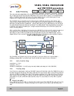
3.3.2.1 With External Reference (Ref I/P)
The delay imposed on the SDI data processed by a frame-synchronising module depends first of all on the
Reference Source selection. If an external, analog Reference signal (e.g. Bi- or Tri-Level Sync) is present
and the
Ref Src
selection control (
VIDEO
:
Ref Src
) is set to
Auto
, the V64xx will automatically operate
as a Frame-Synchroniser, which means that its output will be frame-synchronous to the Reference signal
applied.
In order to keep pace with the incoming SDI data, the Frame-Synchroniser will either repeat a frame or
drop a frame once in a while, depending on a) which of the two clock domains (Input Video versus
Reference signal) is the faster, and b) how far the two clock domains are apart (typically in the range of 0
to ± 150ppm).
Between the events of two successive frame repeats, respectively two frame drops, the input-to-output
delay will gradually increase (or decrease) from a variable minimum value (hysteresis) up to one frame (or
vice versa). Hysteresis is essential in order to prevent a series of frame drops or repeats when
approaching the 'roll-over' point.
As explained earlier, an extra n-field/frame delay can be introduced on top of this variable delay if the 'FD'
option is enabled.
When operating the V64xx as a Frame-Synchroniser, two timing controls (V- & H-Timing) are available for
adjusting the board's output timing relative to the external Reference signal. This works irrespective of the
additional Field/Frame delay, which can be applied on top of the inherent variable delay.
VIDEO
:
V Timing
:
Purpose:
For vertical adjustment (in number of lines)
Range:
-256..+255 lines
VIDEO
:
H Timing
:
Purpose:
For horizontal adjustment (in microseconds)
Range:
from 0µs up to (duration of one line – one pixel)
V6406SY
V6408SY
V6418SY
V6404SY
V6402
V6406SY
V6408SY
V6418SY
V6404SY
V6402


