background image

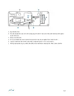
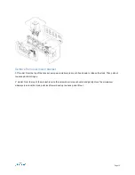
A. Key-Hole Mount (2)
B. AC power supply and power cord with 2-prong plug (AC model). Power cord strain relief assembly with supplied

washer and screw.

C. RJ45 port (PoE model)
D. RJ11 port (elapsed timer and code blue timer model): connection to supplied Timer Switch Control
E. 4 pin port (code blue timer model): connection to supplied 4 pin 30 in. (76.2 cm) connector
F. Setting panel (options vary by model): Mini-USB port, manual dimmer display button, Reset (check-in) button

Page 5

Содержание OneVue Sync Levo C2005

Страница 1: ...Levo Digital Clock and Timer Install Guide OneVue Sync PoE Product Models C2005 X202F Publication date May 4 2020 ...

Страница 2: ...ue is a trademark of Primex All other trademarks are the property of their respective owners Primex is the leading provider of solutions to automate and maintain facility compliance increase efficiencies enhance safety and reduce risk for enterprise organizations in the healthcare education manufacturing and government vertical markets Primex delivers solutions that utilize a facility s existing n...

Страница 3: ...g dimensions 13 Assemble and mount a dual sided digital clock timer 14 Remove from dual mount bracket 15 Install Digital Clock Timer Flush mount 16 Supplied components 16 Dimension specifications 16 Install flush mount clock timer 17 Install Timer Control Switch 19 Step 1 code blue timer only Wire timer to code blue system 19 Step 2 Attach timer to Timer Control Switch 19 Step 3 Mount Timer Contro...

Страница 4: ...display PM indicator light Alternating time and date display option LED digit dimmer option 100 75 50 25 Automatically adjusts for Daylight Saving Time DST If power is interrupted the clock stops until power resumes Upon resumption of power the clock self corrects to the current time Retains time in memory for up to one hour Environment Operating temperature 32 to 95 F 0 to 35 C Storage temperatur...

Страница 5: ...sher and screw C RJ45 port PoE model D RJ11 port elapsed timer and code blue timer model connection to supplied Timer Switch Control E 4 pin port code blue timer model connection to supplied 4 pin 30 in 76 2 cm connector F Setting panel options vary by model Mini USB port manual dimmer display button Reset check in button Page 5 ...

Страница 6: ...pe Weight Max Current Draw Height A Width B Depth C 2 5 6 4 cm 4 digit 1 8 lb 0 8 kg 170 mA 5 0 12 7 cm 10 8 27 3 cm 2 2 5 6 cm 2 5 6 4 cm 6 digit 2 0 lb 0 9 kg 230 mA 5 0 12 7 cm 13 8 34 9 cm 2 2 5 6 cm 4 10 16 cm 4 digit 3 9 lb 1 8 kg 240 mA 8 0 20 3 cm 17 9 45 5 cm 2 4 6 1 cm 4 10 16 cm 6 digit 4 6 lb 2 1 kg 260 mA 8 0 20 3 cm 23 3 59 2 cm 2 4 6 1 cm Page 6 ...

Страница 7: ... injector can be used when an RJ45 port or PoE switch is not available or to perform troubleshooting Ethernet cable CAT 5 or higher AC power wired Ethernet network use A Primex AC power adapter can be used to supply power to allow connection to a wired Ethernet network or when power is not supplied by an RJ45 enabled port or PoE switch Non DHCP network use If a device was assigned to a static IPv4...

Страница 8: ...Distance to wall surface for 18 mounting bracket Dimension G H Mounting bracket screw hole spacing Dimension Clock Timer Model A B C D E F G H 2 5 4 digit 4 bracket 4 8 10 6 2 1 6 0 0 38 0 63 N A 8 0 2 5 2 5 6 digit 4 bracket 4 8 13 6 2 1 6 0 0 38 0 63 N A 8 0 2 5 2 5 4 digit 18 bracket 4 6 10 6 2 2 6 0 N A 2 1 9 5 2 5 2 5 6 digit 18 bracket 4 6 13 6 2 1 6 0 N A 2 1 9 5 2 5 4 4 digit wall mount 8 ...

Страница 9: ... 6 in 15 cm of cord inside the junction box The tilt bracket has a center pass through hole for the 120V pigtail If a junction box is present the tilt bracket has mounting holes spaced to allow direct attachment of the tilt bracket to the junction box cover plate screw holes 1 Mount the tilt bracket directly to the wall with the four 10 screws and anchors supplied To determine the spacing of the s...

Страница 10: ... a screwdriver press each hook down to release the clock and pull out to unsnap bottom hinges 4 model From the top of the bracket insert a thin screwdriver into each notch and gently move the screwdriver sideways to unlock the clock pull clock forward and up to unsnap and lift out Page 10 ...

Страница 11: ...Dimension F Distance to wall surface for 18 mounting bracket Dimension G H Mounting bracket screw hole spacing Dimension Clock Timer Model A B C D E F G H 2 5 4 digit 4 bracket 4 8 10 6 2 1 6 0 0 38 0 63 N A 8 0 2 5 2 5 6 digit 4 bracket 4 8 13 6 2 1 6 0 0 38 0 63 N A 8 0 2 5 2 5 4 digit 18 bracket 4 6 10 6 2 2 6 0 N A 2 1 9 5 2 5 2 5 6 digit 18 bracket 4 6 13 6 2 1 6 0 N A 2 1 9 5 2 5 4 4 digit w...

Страница 12: ...r connections for devices that can be removed without tools A clock timer mounted directly to a wall is required to have a standard power plug Mount the clock timer directly to the wall with the two 10 screws and anchors supplied To determine the spacing of the screws refer to the mounting dimensions Page 12 ...

Страница 13: ... of each other and are monitored and managed as two single devices in OneVue Supplied components Quantity Component 1 Flange mounts to ceiling or wall 1 Bracket bolts to flange and to which two clocks are mounted Required not supplied electrical junction box cord retaining clips Mounting dimensions Mounted Dimensions Clock Type Width from Wall A Height from Ceiling B Depth of 2 Clocks C Dual 2 5 6...

Страница 14: ...nger machine screws provided Wall mount if the mounting location is outside of the junction box break off or cut openings in the flange to route power cords 3 Attach the bracket to the flange using the supplied shorter machine screws nuts and washers 4 For wall mount only knock out power cord break 5 Wire clocks to main power using cord retaining clips to dress wires 6 Align the clock to the brack...

Страница 15: ...wdriver press each hook down to release the clock Then pull out to unsnap bottom hinges 4 model From the top of the bracket insert a thin screwdriver into each notch and gently move the screwdriver sideways to unlock the clock pull clock forward and up to unsnap and lift out Page 15 ...

Страница 16: ...1 Flush mount junction box Material ABS plastic color black and UL Rated 94 V0 1 Bezel material ABS plastic color black and UL Rated 94 V0 4 10 Phillips Flat Head Screw 4 Drywall Anchor Dimension specifications Clock Type Weight Max Current Draw Width A Height B Depth C 2 5 6 4 cm 6 digit 2 0 lb 0 9 kg 230 mA 16 8 42 7 cm 6 5 16 5 cm 3 4 8 6 cm Page 16 ...

Страница 17: ... backup power use only and timer input conduit required for timer models only Do not remove knockouts that you will not be using NOTE For timer models only AC wiring is required to be located to the right side of the junction box divider and the time input to the left side 2 Connect the conduit connection s to the junction box 3 New wall surface only Cut out a 14 in 35 5 cm wide x 5 25 in 13 3 cm ...

Страница 18: ...Figure 1 New wall surface assembly illustration Figure 2 Existing wall surface assembly illustration Page 18 ...

Страница 19: ...Positive Code Blue Input and BLACK Negative Code Blue Input wires to the code blue system Cap off the WHITE and GREEN wires separately 2 An input voltage of 5 120V AC or DC can be used When using DC be sure to use the correct polarity RED wire is positive and the BLACK wire is ground Code Blue start stop events are triggered by the application of voltage across the code blue input wires For code b...

Страница 20: ...ontrol Switch to junction box Timer Control Switch is required to be mounted to a single gang junction box not supplied The junction box dimension is typically 2 25 in x 2 75 in x 4 in 5 72 cm x 6 99 cm x 10 16 cm Page 20 ...

Страница 21: ...can be set to begin its count down or count up from a specific time increment A count up event starts at the 00 00 00 time increment and a count down event starts at the 99 59 00 time increment Either of these can be set to a specific increment through the Timer Switch Control Timer Control Switch overview Count Up and Count Down events are triggered by the use of the three button Timer Control Sw...

Страница 22: ...icates it is in Count Up mode 2 To Start the Count Up event press and release the STOP START button 3 To Stop or Pause the event press and release the STOP START button If the audio buzzer option is enabled the timer emits an audible alarm for 2 seconds and holds the time count 4 To resume a Paused event press and release the STOP START button 5 To automatically stop the current count event and re...

Страница 23: ...nt Up mode 2 Press and Hold the SET CHANGE button for 3 seconds to enter the Set state initially displays _ _ _ _ _ _ and then displays the current set start time The last digit will blink which is the current selected digit 3 Press and release the SET CHANGE button to go to the time increment you want to change then press the INCREMENT button to advance the digit to the desired start time Repeat ...

Страница 24: ...nk which identifies the current selected digit 3 Press and release the SET CHANGE button to advance to the time increment you want to change Then press the INCREMENT button to advance the digit to the desired time value For the example to set a count down to start at 10 minutes you would change the minute increment set to 00 10 00 Repeat this process until you set the time you want to start the co...

Страница 25: ... Code blue mode is indicated by the colon dash and decimal points not being lit in both viewing and counting modes If a code blue active event is in effect it will take priority and a previous task will run in the background until the code blue event has stopped Time duration of the last code blue event is stored in memory and can be viewed until a new code blue event is triggered A code blue coun...

Страница 26: ...Y EXIT for a minimum of four seconds will display the time of the last code blue event Ignored Exits code blue mode and sets timer back to clock mode STOP START INCREMENT Halts stops the code blue event count at the moment the button is pressed Ignored RESET SET CHANGE Ignored Ignored Page 26 ...

Страница 27: ...n wet areas is an electrical hazard and may damage the equipment while nullifying the warranty Device is cleanable with a cloth moistened with water or a common disinfectant Be sure to test any cleaning solutions on a small area of the clock before using it on the entire device Do not use caustic cleaners or abrasives Keep away from dust dirt and moisture For healthcare facilities devices are not ...

Страница 28: ...ry to correct the interference by one or more of the following measures Reorient or relocate the receiver s antenna Increase the distance between the equipment and the receiver Connect the equipment to an outlet on a circuit different from that to which the receiver is connected Consult the dealer or an experienced radio TV technician for help To assure continued appliance any changes or modificat...

Страница 29: ...his product has been altered or modified in any way including but not limited to attempted warranty repair other than by Primex or an authorized service partner Limitation of Liability The warranties and remedies contained herein are exclusive and in lieu of all other warranties express or implied or statutory including any liability arising under any warranty or merchantability or fitness for a p...

Страница 30: ...x products If you have purchased Primex products or have a service agreement with a Primex Partner they are your primary contact for all Technical Support inquires Primex Technical Support Make sure you have satisfied the system requirements that are listed in your product documentation Also you should be at the computer or device on which the problem occurred in case it s necessary to replicate t...

Отзывы: