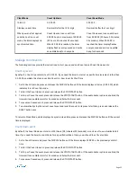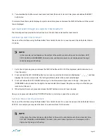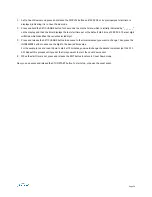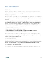
Install Timer Control Switch
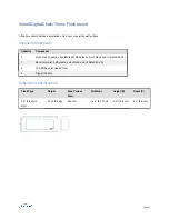
Elapsed Timers and Code Blue Timers include a three-button Timer Control Switch that controls end-user timer events.
• InfoBoards can operate as an Elapsed Timer with both count up and count down options. The three-button Timer
Control Switch allows a user to start, pause, stop, and reset the count events, and set an event to begin at a specific
time increment. When not in an active count event, an InfoBoard displays synchronized time and general messaging.
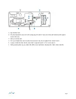
Step 1 (code blue timer only): Wire timer to code blue system
The wiring is dependent on the type of code blue system identified below.
For code blue systems that apply a voltage to start a code blue event.
1. Wire the timer four pin connector RED (Positive Code Blue Input) and BLACK (Negative Code Blue Input) wires to
the code blue system. Cap off the WHITE and GREEN wires separately.
2. An input voltage of 5-120V (AC or DC) can be used. When using DC, be sure to use the correct polarity; RED wire is
positive and the BLACK wire is ground. Code Blue start/stop events are triggered by the application of voltage
across the code blue input wires.
For code blue systems that use a dry contact and do not inject a voltage
•
Wire the timer four pin connector GREEN (Ground) and BLACK (Negative Code Blue Input) wires together and wire
the WHITE (12VDC) and RED (Positive Code Blue Input) wires to the code blue system dry contact.
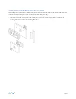
Step 2: Attach timer to Timer Control Switch
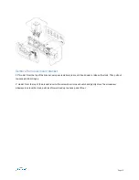
The Timer Control Switch is not connected to the device during shipment. The cable length can be extended up to 100
ft. (30.4 m).
Using the supplied 20 ft. (6.0 m) RJ11 cable, connect the timer to the Timer Control Switch.
Page 19

