background image

83

PRIMERGY BX600 S2 Blade Server System Unit Hardware Guide        

6

T

e

ch
nical

 Information

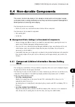
6.4.2 Messages Displayed When a Non-durable 

Components Life has been Reached

The following explains the messages displayed when the non-durable components life has been reached.

Messages are recorded to the event log. The following methods of notification are also available.

• Notifying messages using SNMP trap

• Notifying by e-mail using the alarm handler function

Set the alarm handler before operating the server. Also set the alarm handler to notify MINOR events.

If a message is recorded/displayed, replace the non-durable component that has reached its service life. 

For details about the SNMP settings, refer to "BX600 Management Blade Hardware Guide" and 

"ServerView User's Guide".

For details about alarm handler settings, refer to "BX600 Management Blade Hardware Guide".

Messages displayed when the replacement period for non-durable 
components has been reached 

The Following table explains the messages that are recorded in the event log of the Management Blade, 

and notified by the alarm handler, when non-durable components lives are reached.

If a message is displayed, replace the component that has reached its service life. 

The following table lists each message and the appropriate action.

Messages notified by SNMP trap

The following explains the messages notified by SNMP trap when the lifetime of non-durable 

components has been reached. 

If a message is displayed, check the event log and replace the recorded component that has reached its 

service life. 

The following table lists each message and the appropriate action.

Message Description 

Action 

Rear fans # live time has exceeded the limited count.

System fan unit lifetime has been reached (# indicates 
the number of the system fan unit). Contact an office 
listed in the "Contact Information" of "Start Guide".

Power Supply # live time has exceeded the limited count.

PSU/dummy PSU lifetime has been reached (# 
indicates the number of the PSU slot). Contact an 
office listed in the "Contact Information" of "Start 
Guide".

Message Description 

Action 

Servers % live time has exceeded the limited count.

This message signals that a component's service life 
has been reached. Check the event log and contact an 
office listed in the "Contact Information" of "Start 
Guide". The Management Agent System Name is 
displayed in "%s".

Содержание BX600 S2

Страница 1: ... security features that are provided in order to protect the server hardware and software from theft Chapter 3 Standard Operations This chapter explains such standard operations as turning the server ON OFF and inserting and ejecting floppy disks Chapter 4 Installing Options This chapter explains how to install and remove various options to the chassis Chapter 5 Maintenance This chapter explains h...

Страница 2: ... Products are designed developed and manufactured as contemplated for general use including without limitation general office use personal use household use and ordinary industrial use but are not designed developed and manufactured as contemplated for use accompanying fatal risks or dangers that unless extremely high safety is secured could lead directly to death personal injury severe physical d...

Страница 3: ...bed by their representative characters instead of their exact key face appearance as show below E g Ctrl key Enter key key etc The following indicate the pressing of several keys at once E g Ctrl F3 key Shift key etc Ignoring this symbol could be potentially lethal Ignoring this symbol may lead to injury and or damage the server or internal options A triangle mark emphasizes the urgency of the WAR...

Страница 4: ...manual Windows screens and file names may vary depending on the OS software or configuration of the server used Figures in this manual may not show cables that are actually connected for convenience of explanation CD ROM Drive Descriptions In this manual both CD ROM and DVD ROM drives are described as CD ROM drives Unless otherwise noted a CD ROM drive can also mean a DVD ROM drive Consecutive Ope...

Страница 5: ...ver 2003 R2 x64 Windows Server 2003 2 Windows Microsoft Windows Server 2003 R2 Enterprise x64 Edition Windows Server 2003 R2 Enterprise x64 Edition or Windows Server 2003 R2 x64 Microsoft Windows Server 2003 R2 Standard Edition Windows Server 2003 R2 Standard Edition or Windows Server 2003 R2 Microsoft Windows Server 2003 R2 Enterprise Edition Windows Server 2003 R2 Enterprise Edition or Windows S...

Страница 6: ...ft Corporation in the USA and other countries Linux is a trademark or registered trademark of Linus Torvalds in the USA and other countries Other product names used are trademarks or registered trademarks of their respective manufacturers Other products are copyrights of their respective manufacturers All Rights Reserved Copyright FUJITSU LIMITED 2005 2006 Screen shot s reprinted with permission f...

Страница 7: ...KVM Switch 32 Chapter 4 Installing Options 4 1 Options 34 4 2 Installing Server Blades 36 4 2 1 Before Installing 36 4 2 2 How to Install and Remove 37 4 2 3 LAN Connection in the Chassis 40 4 2 4 Fibre Channel Connection in the Chassis 41 4 3 Installing Network Blades 42 4 3 1 Installing Removing Switch Blades GbE Pass Thru Blades 42 4 3 2 Installing Removing FC Pass Thru Blades 45 4 4 Installing...

Страница 8: ...ifications 65 6 1 3 FC Pass Thru Blade Specifications 66 6 1 4 PSU Specifications 67 6 1 5 Specification of Advanced KVM Module 68 6 1 6 Power Cord Selection 68 6 2 Number of Server Blades that can be Installed 69 6 3 Global Viewer 70 6 3 1 Overview 70 6 3 2 Checking the Operating Environment 71 6 3 3 Startup Procedure 75 6 3 4 Window 75 6 3 5 Global Viewer Setting Menu 77 6 4 Non durable Componen...

Страница 9: ...9 Chapter 1 Component Names and Functions This chapter explains the component names and functions of the server 1 1 Server Front View 10 1 2 Server Rear View 12 ...

Страница 10: ... be damaged LED status Server Status ON Green The main power supply of the chassis is ON ON Amber The AC power is ON but the main power supply of the chassis is OFF OFF The main power supply or the AC power of the chassis is OFF 4 Front maintenance switch LED This works in conjunction with the rear maintenance LED and lights blinks in the following situations 5 Front maintenance switch Pressing th...

Страница 11: ... disk as follows 8 Server blade power LED 9 Server blade power switch 1 0 KVM select LED 1 1 KVM select switch Selects the keyboard display mouse 1 2 Fibre Channel active link display LED 1 3 LAN active link display LED This LED lights or blinks depending on the status of the server blade LAN transmission as follows 1 4 Display USB expansion connector 1 5 2 5 inch storage bay Contains a BX620 S3 S...

Страница 12: ... used 6 KVM connector Connect the KVM cable and then connect the keyboard display and mouse 7 Rear maintenance LED This works in conjunction with the front maintenance LED and lights blinks in the cases below The LED colors vary depending if the default KVM module is used or an optional advanced KVM module is installed 8 Rear maintenance switch Pressing this switch turns the front and rear mainten...

Страница 13: ... Blinking Amber A link has not been established with the external fibre channel device Blinking Green Blinking Amber There is an error in the Fibre Channel Expansion Board installed in the server blade of the target connector or the FC Pass Thru Blade Contact an office listed in the Contact Information of Start Guide or device administrator 1 2 Fibre Channel connector Install the optional SFP modu...

Страница 14: ...art Guide or device administrator 2 5 Warning LED It lights depending on the status of the PSU as follows 2 6 AC Power LED Lights or blinks depending on the status of the AC power of the PSU as follows There is no AC power LED in the dummy PSU 2 7 System fan module LED The LED is lit in green when a fan module is installed in the system fan unit The upper LED is for fan module 1 and the lower LED ...

Страница 15: ...agement Blade LAN transfer as follows Also it may blink uniformly when NIC diagnostic function of the Management Blade is used 3 4 LAN link LED Lights depending on the connection status of the Management Blade LAN as follows LED status Server Status Blinking Amber Data is being transferred LED status Server Status ON Green LAN link is being established ...

Страница 16: ...16 Chapter 1 Component Names and Functions ...

Страница 17: ...17 Chapter 2 Security This chapter explains the security features that are provided in order to protect the server hardware and software from theft 2 1 Security 18 ...

Страница 18: ...k the rack door to protect the hardware in the rack from theft To close the rack door shut the door and return the rack handle and turn the rack key Do not lose the rack key If the key is lost contact an office listed in the Contact Information of Start Guide For instructions on opening the rack door refer to 3 1 Opening the Rack Door pg 22 The above explanation is based on the 40U standard rack F...

Страница 19: ...not use the server Perform password settings in the following blades For details about the settings of other optional devices refer to the PRIMERGY ServerBooks supplied with the server and the Supplement supplied with each option Management Blade For details refer to BX600 Management Blade Hardware Guide Switch Blade For details refer to BX600 Switch Blade PG SW103 Hardware Guide Server blade For ...

Страница 20: ...20 Chapter 2 Security ...

Страница 21: ...h standard operations as turning the server ON OFF and inserting and ejecting floppy disks 3 1 Opening the Rack Door 22 3 2 Turning On the Server 24 3 3 Turning Off the Server 26 3 4 Inserting and Ejecting a Floppy Disk 28 3 5 CD ROM Drive 30 3 6 KVM Switch 32 ...

Страница 22: ... to open the front and rear doors of the 40U standard rack Refer to the manual provided with the rack for procedures on opening other rack doors Opening the Front Door 1 Turn the rack key and pull the rack handle up 2 Turn the handle in the direction of the arrow and pull Turn and pull ...

Страница 23: ...he rack handle up 2 Turn the handle in the direction of the arrow and pull Unless you are inserting ejecting media or turning the power on off keep the door closed Doing so blocks electric waves from cell phones etc Do not lose the keys If the key is lost contact an office listed in the Contact Information of Start Guide Turn and pull ...

Страница 24: ...onment range 10 35 C For details about the operating environment refer to Start Guide and Safety Precautions When operating the device outside of this operating environment the server may operate improperly damage data etc When operating the device outside of this operating environment Fujitsu cannot be held responsible for any related damage malfunction or loss of data etc The fans rotate at high...

Страница 25: ...y abnormalities are detected by POST error messages are displayed User s Guide 9 2 Troubleshooting When server blade is set to network activation PXE after turning on the main power supply of the chassis wait at least one minute before turning on the power of the server blade In that time the Switch Blade is not completely activated or the reconfiguration of the network is not complete Power LED i...

Страница 26: ...re is not followed correctly In the event of smoke or sparks immediately unplug the power plug from the outlet Failure to do so may lead to a fire or electric shock Be sure to wait for 10 seconds or longer after server blade shutdown before turning the server on If the power is turned on straight after shutdown it may cause a server error or failure Wait for 20 seconds before removing the server b...

Страница 27: ...t Standby Hibernation or Shut down normally Shut down is specified For Windows 2000 Server Standby Hibernation Power off normally Power off is specified On this server blade functions corresponding to Standby and Hibernation are supported as BIOS and hardware functions However some drivers and software installed in the server blade do not support these functions For this reason functions correspon...

Страница 28: ...loppy disk to any fluids Do not open the shutter of the floppy disk and touch the disk surface Do not bend the floppy disk or place heavy objects on it Do not expose the floppy disk to strong magnetic fields Do not drop the floppy disk on hard surfaces Do not store the disk in extremely hot or cold conditions Do not put layers of labels on the floppy disk Keep the floppy disk away from condensatio...

Страница 29: ...sk drive from the side with the shutter After clicking into place the floppy disk eject button pops out Ejecting the Floppy Disk Make sure that the floppy disk access LED is off Press the floppy disk eject button The floppy disk is ejected Do not eject the floppy disk while the floppy disk access LED is on The data stored on the floppy disk may be damaged Floppy disk eject button Shutter Face the ...

Страница 30: ...he CD ROM Do not disassemble the CD ROM drive unit Clean the CD ROM tray before use Use a dry cloth to clean the CD ROM tray If out of use for a long period of time in order to prevent an accident eject the CD ROM from the CD ROM drive Also to prevent dust getting into the CD ROM drive unit keep the CD ROM tray closed CD ROM When removing a CD ROM from its case press on the centre of the case as s...

Страница 31: ...uddenly from a cold area outdoors to a warm area water droplets will appear on the surface and the CD ROM drive unit may not be able to read the data In this case wipe with a soft dry cloth and then leave to dry naturally Do not dry using a hair dryer etc To prevent dust scratches and changing shape store in a case when not in use Do not store in areas with direct sunlight near heating appliances ...

Страница 32: ...assis Perform KVM switching operations using one of the following methods Press the KVM select switch of the server blade Use the Management Blade from the management terminal and perform switching operations BX600 Management Blade Hardware Guide When KVM switching operations are performed consecutively confirm that the selected server blade has completely switched by checking the KVM selected LED...

Страница 33: ...tall and remove various options to the chassis 4 1 Options 34 4 2 Installing Server Blades 36 4 3 Installing Network Blades 42 4 4 Installing the PSU 49 4 5 Installing Advanced KVM Module 53 4 6 Replacing the Management Blade 57 4 7 Replacing the System Fan Unit 58 ...

Страница 34: ...upplement supplied with each option Do not disassemble the PSU Doing so may cause electric shock Do not install unauthorized third party internal options Doing so may cause a device failure fire or electric shock Do not damage or modify internal cables or devices Doing so may cause a device failure fire or electric shock Front Server blade Switch Blade GbE Pass Thru Blade FC Pass Thru Blade etc PS...

Страница 35: ...ling options first touch a metal part of the chassis to discharge static electricity Do not touch the circuitry on boards Hold the brackets or the edges of the circuit boards If devices are installed or removed other than by the methods outlined in this chapter the warranty will be invalidated ...

Страница 36: ...owing points Installable server blade The following server blade can be installed to the chassis BX620 S2 Server Blade BX620 S3 Server Blade Always turn off the power of the server blade 3 3 Turning Off the Server pg 26 Check that the system fan unit is operating correctly before installing or removing the blade server If it is broken the blade server cannot be installed removed during operation B...

Страница 37: ...pg 40 The server blade slot numbers are indicated below 4 2 2 How to Install and Remove How to remove server blades 1 Turn off the server blade Turn off the server blade you wish to remove 3 3 Turning Off the Server pg 26 2 Touch a metal part of the chassis to discharge static electricity 3 Remove all cables etc connected to the server blade Remove the display USB cables connected to the server bl...

Страница 38: ...dummy server blade Remove any server blade dummy server blade installed to the slot for installation No server blade dummy server blade is installed at the time of purchase This procedure is not required for the first installation How to remove server blades pg 37 When multiple server blades are installed to the chassis before removing use the server blade identification function to check the posi...

Страница 39: ...ver blade is the same as that for installing the server blade 3 Disconnect cables when using the expansion card slot module When drawing out the cables connected to the expansion card slot create space in the lower part of the chassis and pull towards the back of the server Before installing the server blade check there is no dust in the blade connector Before closing the release latch make sure t...

Страница 40: ...ch Blade slot 2 4 NET2 NET4 Port 1 2 3 4 5 6 7 8 9 10 Network blade slot 3 Network blade slot 1 Port 1 2 3 4 5 6 7 8 9 10 Server blade slot 1 1 2 1 2 1 2 Server blade slot 3 1 2 1 2 1 2 Server blade slot 4 1 2 1 2 1 2 Server blade slot 2 1 2 1 2 1 2 Server blade slot 5 1 2 1 2 1 2 Server blade slot 6 1 2 1 2 1 2 Server blade slot 7 1 2 1 2 1 2 Server blade slot 9 1 2 1 2 1 2 Server blade slot 10 1...

Страница 41: ... the following diagram and install SFP modules to the correct position For BX620 S2 BX620 S3 Server Blade Network blade slot 3 Network blade slot 4 Network blade slot 3 Port 1 2 3 4 5 6 7 8 9 10 Server blade slot 10 1 2 Server blade slot 9 1 2 Server blade slot 8 1 2 Server blade slot 7 1 2 Server blade slot 6 1 2 Server blade slot 5 1 2 Server blade slot 4 1 2 Server blade slot 3 1 2 Server blade...

Страница 42: ... following manuals Switch Blade BX600 Switch Blade PG SW103 Hardware Guide GbE Pass Thru Blade manual supplied with GbE Pass Thru Blade Before installing Notes when installing and removing Switch Blades can be installed removed when the main power of the chassis is turned on In this case note the following points If the server blade connected to a Switch Blade GbE Pass Thru Blade is operating disc...

Страница 43: ...ade GbE Pass Thru Blade PG LNB101 User s Guide How to remove Switch Blade GbE Pass Thru Blade 1 Touch a metal part of the chassis to discharge static electricity 2 Remove all LAN cables connected to the Switch Blade GbE Pass Thru Blade 3 Remove the Switch Blade GbE Pass Thru Blade Grip and pull on the handle 1 pull the Switch Blade GbE Pass Thru Blade towards you and remove it 2 The figure shows a...

Страница 44: ... handle 2 The figure shows an example using Switch Blade The procedure for installing the dummy Switch Blade is the same as that for installing the Switch Blade LAN Pass Thru Blade 4 Install a LAN cable to Switch Blades GbE Pass Thru Blades When multiple Switch Blades GbE Pass Thru Blades are installed to the chassis before removing use the Switch Blade GbE Pass Thru Blade identification function ...

Страница 45: ...Available FC Pass Thru Blade The following shows the type of FC Pass Thru Blade used for this chassis Included FC Pass Thru Blade options Before installing the FC Pass Thru Blade refer to 6 1 3 FC Pass Thru Blade Specifications pg 66 and check the included options When removing the FC Pass Thru Blades or dummy Switch Blade do not insert your hand into the FC Pass Thru Blades blade slot Doing so ma...

Страница 46: ...ove it 2 5 Install the network blade dummy Switch Blade How to install Switch Blades GbE Pass Thru Blades pg 44 How to install a FC Pass Thru blade pg 47 The procedure for removing the dummy Switch Blade is the same as that for removing the Switch Blade Be sure to keep the removed dummy Switch Blades for later use 4 3 1 Installing Removing Switch Blades GbE Pass Thru Blades pg 42 After removing th...

Страница 47: ... How to remove FC Pass Thru Blades pg 46 3 Install a FC Pass Thru Blade Insert the Fibre Channel Pass Thru Blade 1 and set the handle 2 The procedure for installing the dummy Switch Blade is the same as that for installing the Switch Blade 4 3 1 Installing Removing Switch Blades GbE Pass Thru Blades pg 42 Before installing the FC Pass Thru Blade check there is no dust in the blade connector When i...

Страница 48: ...O Module PG FCD101 the SFP module is supplied with the expansion board for all other users the SFP module is sold separate 5 Remove the cap of the SFP module and connect the Fibre Channel cable Be sure to install with the lever raised If the lever is raised after inserting the SFP module with the lever down the lock is unlocked and the SFP module becomes loose Check that the Fibre Channel cable co...

Страница 49: ...4 4 1 Before Installing the PSU Notes when redundancy of the power supply is enabled Conditions for the power redundancy function To enable redundancy of the power supply it is necessary to add two PSUs Available PSU The following shows PSU types used for this chassis Do not disassemble the PSU Doing so may cause electric shock or fire When installing or removing PSUs from the server be sure to tu...

Страница 50: ...Removing the PSU This section explains how to install remove PSUs How to install a PSU 1 Turn off the server blade and the main power supply of the chassis 3 3 Turning Off the Server pg 26 2 Touch the metal part of the chassis to discharge static electricity 3 Press the handle release latch 1 and pull down the handle of the dummy PSU 2 Rear of the chassis PSU slot4 Optional PSU slot3 Optional PSU ...

Страница 51: ...ll it down 2 Using both hands insert the PSU into the PSU slot 1 and pull up the handle 2 When installing a PSU check that the connector pins at the rear of the PSU are not damaged or bent Check that PSU is inserted firmly to the back of the PSU slot 6 Connect the power supply cable to the PSU Start Guide How to remove a PSU To remove simply reverse the installation procedure in How to install a P...

Страница 52: ... failed PSU or ServerView After removing the PSU be sure to replace it with a new unit How to replace a PSU 1 Disconnect the power cable of the PSU Start Guide 2 Remove the broken PSU How to remove a PSU pg 51 3 Install the new PSU How to install a PSU pg 50 4 Connect the power supply cable to the replaced PSU Do not operate when the PSU or dummy PSU has been removed When installing removing a PSU...

Страница 53: ...mulate virtualize the floppy disk drive CD ROM drive connected to the remote terminals and the server blades can share the drives The advanced KVM module of the server supports the following functions Graphic mode console redirection Remote USB floppy disk emulation Remote USB CD ROM emulation Remote boot function from the emulated USB device 4 5 1 Before Installing Advanced KVM Module KVM module ...

Страница 54: ...s Before installing an advanced KVM module refer to 6 1 5 Specification of Advanced KVM Module pg 68 to check the included options 4 5 2 Installing Removing Advanced KVM Module How to install an advanced KVM module 1 Turn off the server blade and the main power supply of the chassis 3 3 Turning Off the Server pg 26 2 Touch the metal part of the chassis to discharge static electricity Product name ...

Страница 55: ... screws fixing the KVM module installed by default 4 Remove the default KVM module Hold the handle out 1 and pull the KVM module forward to remove 2 5 Install an advanced KVM module Press the KVM module while the handle is opened forward 1 and set the handle inside 2 Screw 1 2 Handle 1 2 Handle ...

Страница 56: ...hapter 4 Installing Options 6 Secure the module using screws removed in step 3 How to remove an advanced KVM module To remove an advanced KVM module follow the removal procedures for the default KVM module ...

Страница 57: ...place the Management Blade without turning off the main power supply of the chassis or the server blade hot swap hot plug responsive Check the slot position of the failed Management Blade using the Management Blade error LED or ServerView For details about Management Blade refer to BX600 Management Blade Hardware Guide Management Blade slot Management Blades are installed to all the slots by defau...

Страница 58: ...an has failed using the rear LED or ServerView System fan unit redundancy System fan is configured as follows System fan unit 1 internal fan 2 System fan unit 2 internal fan 2 Replace the fan unit within 2 minutes of removing the broken one from the server When removing a fan unit during operation always check that one fan is operating normally When removing the fan unit do not touch the fan unit ...

Страница 59: ...59 Chapter 5 Maintenance This chapter explains how to perform daily maintenance and the maintenance information 5 1 Cleaning 60 5 2 System Event Log 62 ...

Страница 60: ...Interior In dusty environments dust deposits in the server Dust deposits may cause a server failure fire or electric shock To keep the PRIMERGY server in good condition use a vacuum cleaner periodically to remove dust deposits Cleaning components CPUs Dust deposits must be removed because it will impair the cooling performance Fans Remove dust from and around the fans Memory expansion cards Remove...

Страница 61: ...a to from a floppy disk correctly Clean the head once every three months 5 1 4 Optional Devices For details about cleaning optional devices refer to the PRIMERGY ServerBooks supplied with the server and the Supplement supplied with each option Be careful when removing components such as CPUs memory modules or hard disk units Be sure to install parts and cables in the original position Leaving dust...

Страница 62: ...nce 5 2 System Event Log The chassis management is performed on the Management Blade For event logs relating to the chassis refer to the Management Blade event logs For details refer to BX600 Management Blade Hardware Guide ...

Страница 63: ...ical Information This chapter explains the specifications and operational notes of the server 6 1 Specifications 64 6 2 Number of Server Blades that can be Installed 69 6 3 Global Viewer 70 6 4 Non durable Components 81 ...

Страница 64: ... Blade Standard 0 Max 2 Redundant Depending on network configuration Hot plug Yes KVM Module Adv KVM Module option Standard 1 Max 1 Redundant No Hot plug No External I O port 1 Keyboard mouse video LAN 1 when adv KVM module is installed SCSI 2 when SCSI module is installed Keyboard Mouse Option Dimension Width Depth Height 446 735 308 mm 7U Weight Maximum 130 kg server blade installation Power con...

Страница 65: ... a standard option check that the following items are supplied with it before use Please contact an office listed in the Contact Information of Start Guide if any parts are missing Packaged Items Switch Blade 1 Specifications Item Function specification Product ID PG SW103 I O port Internal 10 ports 1Gbps External 3 ports 1000BASE T 100BASE TX 10BASE T selective Dimension W D H 35 250 130 mm not i...

Страница 66: ...on check that the following items are supplied with it before use Please contact an office listed in the Contact Information of Start Guide if any parts are missing Packaged Items FC Pass Thru Blade 1 Specifications Item Function specification Product ID PG FCB101 I O port Internal 10 ports Max 2Gbps External 10 ports 2Gbps Fibre Channel SFP cage Dimension W D H 35 250 130 mm not including the pro...

Страница 67: ...it before use Please contact an office listed in the Contact Information of Start Guide if any parts are missing Packaged Items PSU 2 200V power cable 2 The attached power cables cannot be used Prepare power cables that conform with the standards in your country Specifications Item Function specification Product ID PG PU118 Input voltage 200 240V AC 50 60Hz Power capacity 2100W during 200V operati...

Страница 68: ...ntact Information of Start Guide if any parts are missing Packaged Items Advanced KVM Module 1 Specifications 6 1 6 Power Cord Selection Use power cables that conform with the commercial power supply standard of your country They should also meet the following specifications Item Function specification Product ID PG KVB101 I O port Keyboard Mouse PS 2 Video output 10BASE T 100BASE TX LAN connector...

Страница 69: ...more server blades or switch blades When additionally purchasing a server blade check the number of server blades If there are too many server blades the safety mechanism of the power control device may prevent the power of the server blade being turned on When using the VLAN function of the Switch Blade to split the network into two or more a server blade cannot be installed to server blade slot ...

Страница 70: ... resolution supported by the Global Viewer are as follows Screen redirection and VGA output are shared by all server blades and only one server blade can use the device at a time The following indicates the various modes that are supported at each resolution Item Description Frame resolution Text mode 640 400 Graphic mode 640 480 800 600 1024 768 Frame frequency 56Hz 60Hz 70Hz 72Hz 75Hz 85Hz RGB c...

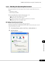
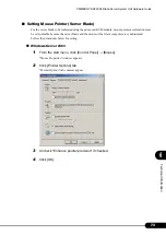
Страница 71: ...rol of the client computer is set to enabled Setting ActiveX Control Client pg 71 Mouse pointer acceleration of the server blade to be redirected is set to disabled Setting Mouse Pointer Server Blade pg 73 Setting ActiveX Control Client Limit to ActiveX controls in the trusted sites of the client computer Follow the procedures below to add the advanced KVM module to the trusted sites and set Activ...

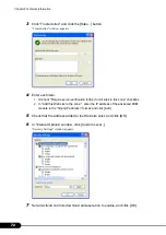
Страница 72: ... all sites in this zone checkbox 2 In Add this Web site to the zone enter the IP address of the advanced KVM module in the http IP address format and click Add 5 Check that the address added to the Web site exist and click OK 6 In Internet Options window click Custom Level Security Settings window appears 7 Set all ActiveX controls download and execution to enable and click OK ...

Страница 73: ...mouse pointer acceleration must be set to disable because the server blade and the mouse of the client computer are synchronized Follow the procedures below for setting Windows Server 2003 1 From the start menu click Control Panel Mouse Mouse Properties window appears 2 Click Pointer Options tab Pointer Options tab contents appear 3 Uncheck Enhance pointer precision if checked 4 Click OK ...

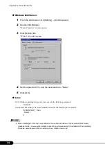
Страница 74: ...lick OK Linux For X Window operating system on Linux execute the following command xset m 1 To automate this setting it is recommended to describe the following in etc profile if DISPLAY then xset m 1 fi When installing an OS to the server blade on the redirection window of the advanced KVM module graphical mode mouse synchronization cannot be performed during OS installation When installing Windo...

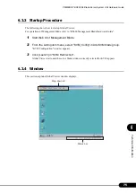
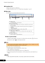
Страница 75: ... refer to BX600 Management Blade Hardware Guide 1 Start Web UI of Management Blade 2 From the setting item menu select KVM_Config in Adv KVM blade group KVM Configuration window appears 3 Click Launch in KVM Redirection Global Viewer starts and the server blade window currently selected for KVM appears 6 3 4 Window This section explains Global Viewer window displays Status bar Drop down list ...

Страница 76: ...nu bar scroll bar and status bar on the Global Viewer window When using Global Viewer window it is necessary to synchronize the mice at all times 1 Message area An area that displays various messages 2 Key code setting area This area is used to combine set keys with mouse click and key operations from the client computer Clicking Ctrl Alt or Shift switches the target key and the operating key is h...

Страница 77: ...and floppy disk drive of the client computer to be emulated Storage menu pg 79 Video Save read the window display and setting values Video menu pg 80 Help Clicking About displays Global Viewer firmware version Item Description Full Screen Displays full screen of Global Viewer window Alt Enter Alt Enter key Alt Escape Alt Escape key Alt F4 Alt F4 key Alt Space Alt Space key Alt SysReq Alt SysReq ke...

Страница 78: ...led in the slot When a server blade is selected and the same server blade is selected again emulated USB device will be removed Image Response Time Fast at time of purchase High Middle Low Set the window image response time The faster the response time is set the more LAN bandwidth increases Image Sampling 4 1 1 at time of purchase 4 4 4 Set the color strength The 4 1 1 setting decreases LAN bandw...

Страница 79: ...ecognizes Open HDD Image File Previously saved hard disk images are emulated Note Performing emulation only does not enable the floppy disk drive to be used It is necessary to mount the floppy disk drive and to select USB Switch Mount Floppy Drive UnMount Floppy Drive Mount unmount the virtual floppy disk drive to the advanced KVM module Mount Floppy Drive Mount the virtual floppy disk drive to th...

Страница 80: ...red green and blue scale bars separately Contrast Adjust contrast of the Global Viewer window by operating primitive signal red green and blue scale bars separately Auto Adjust Automatically adjust the window brightness and contrast During the adjustment for approximately 10 seconds the window is locked Load Default Setting Load the default settings Save Configuration Save the current setting info...

Страница 81: ... shutdowns Non durable components are supposed to be replaced in the periodical maintenance performed after these messages appear These parts can be continuously used for approximately one year after the message 6 4 1 Component Lifetime Information Browse Setting Menu The running hours and lifetime of the non durable components of this server can be displayed using the management tools from the ma...

Страница 82: ...to a temperature environment ranging from 10 35 C These values will drop by approximately half with a 10 C increase in temperature The lifetime of non durable components fluctuates according to the ambient temperature The lifetime of such components is calculated on the assumption that the server is used at an annual average temperature of 25 C Thus if the server is used in an environment where th...

Страница 83: ...he alarm handler when non durable components lives are reached If a message is displayed replace the component that has reached its service life The following table lists each message and the appropriate action Messages notified by SNMP trap The following explains the messages notified by SNMP trap when the lifetime of non durable components has been reached If a message is displayed check the eve...

Страница 84: ...84 Chapter 6 Technical Information ...

Страница 85: ...lade Installation 44 Removing 43 H Hard disk access display LED 11 Hard disk failure LED 11 Hard disk status LED 11 I Inlet 14 Installing options 34 K KVM module Installation 54 Removing 56 KVM select LED 11 KVM select switch 11 KVM Switch 32 L LAN active LED 13 14 15 LAN active link display LED 11 LAN connection in the Chassis 40 LAN link LED 13 14 15 LAN link operation LED 14 LAN speed LED 14 M ...

Страница 86: ...LED 11 Server blade power switch 11 Server blade slot 10 11 Switch Blade Installation 44 Removing 43 Switch Blade maintenance LED 13 System event log 62 System fan module error LED 14 System fan module LED 14 System fan unit 12 T Turn OFF 26 ON 24 W Warning LED 14 ...

Страница 87: ...rty copyrights or other rights arising from the use of any information in this manual No part of this manual may be reproduced in any without the prior written permission of Fujitsu PRIMERGY BX600 S2 Blade Server System Unit Hardware Guide B7FH 4071 02EN 00 Issued on Issued by July 2006 FUJITSU LIMITED ...

Отзывы: