background image

Quantum 1402

                            www.quantumrehab.com

11

I I .   S A F E T Y

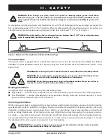
5  (8.7%)

Figure 1. Maximum Safe Angle (Ascending and Descending)

WARNING! Even though your power chair is capable of climbing slopes greater than those

illustrated in figure 1, do not, under any circumstances, exceed the incline guidelines or any

other specifications presented in this manual. Doing so could cause instability in your power

chair.

In compliance with the Americans with Disabilities Act of 1990, all handicap public access ramps are required to
have a maximum slope of 5° (8.7%). Therefore, Pride recommends that the maximum slope of an incline you
attempt to safely ascend or descend on your power chair does not exceed 5° (8.7%). See figure 1.

WARNING! Any attempt to climb or descend a slope steeper than 5° (8.7%) may put your power

chair in an unstable position and cause it to tip.

Freewheel Mode

Your power chair is equipped with two manual freewheel levers to allow for manual maneuverability by a trained
attendant. For more information about how to place your power chair into and out of freewheel mode, see III. “Your
Power Chair.”

WARNING! Do not use your power chair in freewheel mode without an attendant present.

WARNING! Do not attempt to personally place your power chair in freewheel mode

while seated on it. Ask an attendant for assistance if necessary.

WARNING! Do not place your power chair in freewheel mode while on an incline or

decline. The chair could roll uncontrollably on its own.

Braking Information

Your power chair is equipped with two powerful brake systems:

!

Regenerative — uses electricity to rapidly slow the vehicle when the joystick returns to the center/stop position.

!

Disc Park Brake — activates mechanically after regenerative braking slows the vehicle to near stop, or when
power is removed from the system for any reason.

Cornering Information

While your power chair is equipped with rear caster wheels and front anti-tip wheels, excessively high cornering
speeds can still create the possibility of tipping. Factors which affect the possibility of tipping include, but are not
limited to: cornering speed, steering angle (how sharply you are turning), uneven road surfaces, inclined road
surfaces, riding from an area of low traction to an area of high traction (such as passing from a grassy area to a
paved area – especially at high speed while turning), and abrupt directional changes. High cornering speeds are
not recommended. If you feel that you may tip over in a corner, reduce your speed and steering angle (i.e., lessen
the sharpness of the turn) to prevent your power chair from tipping.

WARNING! When cornering sharply, reduce your speed and maintain a stable center of gravity.

This greatly reduces the possibility of a tip or fall.

Содержание QUANTUM 1402

Страница 1: ...QUANTUM S E R I E S 1 800 800 8586 US 1 888 570 1113 Canada INNOVATIVE REHAB SOLUTIONS Including Model Quantum 1402...

Страница 2: ...echnician must perform the initial setup of this power chair and must perform all of the procedures in this manual The symbols below are used throughout this owner s manual and on the power chair to i...

Страница 3: ...3 I INTRODUCTION 4 II SAFETY 5 III YOUR POWER CHAIR 17 IV ASSEMBLY 21 V COMFORT ADJUSTMENTS 23 VI DISASSEMBLY 29 VII BATTERIES AND CHARGING 30 VIII CARE AND MAINTENANCE 35 IX WARRANTY 41 C O N T E N...

Страница 4: ...t you promise that you will not change alter or modify this product or remove or render inoperable or unsafe any guards shields or other safety features of this product fail refuse or neglect to insta...

Страница 5: ...ires Use correct tie down points for controller harness to prevent the harness from getting caught in the drive tires or pinched in the seat frame or damaged when passing through doorways Avoid exposu...

Страница 6: ...icle while seated in it Do not connect an extension cord to the AC DC converter or the battery charger Removal of grounding prong can create electrical hazard If necessary properly install an approved...

Страница 7: ...leakage or explosive conditions Keep tools and other metal objects away from battery terminals Battery Set Configuration Positive Red Terminal Post Negative Black Terminal Post Connect Red wire to Re...

Страница 8: ...ycling of your Pride product and its packaging Locked and in drive mode Place unit on level ground and stand to one side when changing from drive mode to freewheel mode or freewheel mode to drive mode...

Страница 9: ...ractice Simply take your time and you will soon be in full and confident control as you maneuver through doorways on and off of elevators up and down ramps and over moderate terrain Below are some pre...

Страница 10: ...amp or other incline Take wide swings with your power chair s front wheels around any tight corners If you do that the power chair s rear wheels will follow a wide arc not cut the corner short and not...

Страница 11: ...le seated on it Ask an attendant for assistance if necessary WARNING Do not place your power chair in freewheel mode while on an incline or decline The chair could roll uncontrollably on its own Braki...

Страница 12: ...ravel and sand If you feel unsure about a driving surface avoid that surface Inclement Weather Precautions Exposure of your power chair to inclement weather conditions should be avoided whenever possi...

Страница 13: ...anufacturer of the lift elevation product before using that product WARNING Never sit on your power chair when it is being used in connection with any type of lift elevation product Your power chair w...

Страница 14: ...or move a power chair by any of its removable parts including the armrests seat foot riggings controller and shrouds Preventing Unintended Movement WARNING If you anticipate being seated in a station...

Страница 15: ...e power chair from tipping forward during transfer WARNING Avoid putting all of your weight on the power chair armrests and do not use the armrests for weight bearing purposes such as transfers Such u...

Страница 16: ...gency vehicles In some cases these waves can cause unintended movement or damage to the control system Every electrically powered mobility vehicle has an immunity or resistance to EMI The higher the i...

Страница 17: ...the armrests seatback and controller The power base assembly includes two drive wheels two anti tip wheels two rear caster wheels a power seat connector optional harness connectors and a body shroud S...

Страница 18: ...ve loads the main circuit breaker trips to prevent damage to the motors and the electronics If the circuit trips allow your power chair to rest for approximately one minute Next push in the circuit br...

Страница 19: ...he desired position WARNING Do not use the freewheel lever handles as tie down points to secure this product I I I Y O U R P O W E R C H A I R Figure 8 Drive Mode left side shown Figure 7 Freewheel Mo...

Страница 20: ...ving over rough terrain and up and down curbs This system works by allowing the caster forks to respond to weight transfers and uneven terrain The rear caster wheels will pivot as you drive over obsta...

Страница 21: ...d to the power base with the Universal Mounting System UMS The UMS consists of universal parts that may be attached to any medium back or high back seat regardless of seat width or seat depth The two...

Страница 22: ...ange the trapeze bar height see V Comfort Adjustments 2 Tilt the seat back and slide the rear extrusion onto the rear trapeze bar See figure 10 3 Lower the front extrusion onto the front trapeze bar u...

Страница 23: ...onent weights before you disassemble the power chair WARNING Remove the occupant from the power chair before making any adjustments You may need the following to make comfort adjust ments metric stand...

Страница 24: ...INGSCREW ARMRESTHEIGHT ADJUSTING SETSCREWS ARMRESTANGLE ADJUSTINGSCREW Figure 14 Seat Position Adjustment 10 Move the seat towers up or down to the desired height 11 Reinstall the ball detent pin into...

Страница 25: ...t or change the position of the controller for either left hand or right hand use MANDATORY Prevent controller harness damage Avoid routing the controller harness on the outside of the armrest pad Rou...

Страница 26: ...ot platform depth 1 Remove the nuts and bolts from the foot platform bracket Seefigure17 2 Move the foot platform in or out to the desired depth 3 Reinstall the nuts and bolts into the foot plat form...

Страница 27: ...ing seat option is equipped with a system that reduces the speed of the power chair by one half when the seat is el evated more than 1 2 inches 2 5 5 cm Always check to be sure this system is operatin...

Страница 28: ...ip bracket located right after the shock strut See figure 20 2 Turn the locknut counterclockwise to loosen 3 Place your wrench on the adjustable cam located on the other side of the locknut See figure...

Страница 29: ...power base To remove a power seat 1 Turn off the power to the controller 2 Disconnect the controller from the electronics tray 3 Release the seat by moving the seat release lever backward 4 Lift up th...

Страница 30: ...for easy viewing See figure 6 The ammeter indicates the rate of charge being administered to fully recharge the batteries It is also a good indication of whether or not the charger is working The amm...

Страница 31: ...much charge is needed to fully charge the batteries Wait about a minute for the charger to warm up The ammeter may move as high as 5 5 amps then gradually move back down to 0 amps as the batteries cha...

Страница 32: ...le When the battery is fully charged the amperage from the charger is nearly at zero This is how the charger maintains a charge but does not overcharge the battery Can I use a different battery charge...

Страница 33: ...ttery types Deep cycle batteries are specifically designed to provide power drain down their charge and then accept a relatively quick recharge AGM and Gel Cell batteries should be charged as often as...

Страница 34: ...g NOTE If you are storing a power chair for an extended period of time you may wish to block the unit up with several boards under the frame This keeps the tires off the ground and prevents the possib...

Страница 35: ...ound take your power chair to a Quantum Rehab Specialist Power chairs that are frequently exposed to sources of water such as incontinence should be inspected often for corrosion and electronic compon...

Страница 36: ...ion Contact your Quantum Rehab Specialist if necessary Ensure that all parts of the controller system are securely fastened to your power chair Do not overtighten any screws Check for proper tire infl...

Страница 37: ...plastic and metal parts of your power chair Avoid using products that may scratch the surface of your power chair If necessary clean your product with an approved disinfectant Make sure the disinfecta...

Страница 38: ...ement Adiagram is printed on a decal on your power chair frame near the battery tray See figure 26 MANDATORY Battery posts terminals and related accessories contain lead and lead compounds Wear goggle...

Страница 39: ...ame battery 14 Install the battery into the front of the battery tray with the battery s terminals facing inward toward the center of the power chair Plug the wiring harness into a quick disconnect WA...

Страница 40: ...nections If the above conditions prove normal you can load test the batteries with a battery load tester These testers are available at automotive parts stores Disconnect both batteries before load te...

Страница 41: ...ounting brackets 18 MONTH LIMITED WARRANTY For eighteen 18 months from the date of purchase Pride will repair or replace at our option to the original purchaser free of charge any of the following par...

Страница 42: ...ANTY SERVICE Warranty service must be performed by a Quantum Rehab Specialist Do not return faulty parts to Pride without prior written authorization All transportation costs and shipping damage incur...

Страница 43: ...re 27 Width See figure 27 Drivetrain Two motor mid wheel Batteries Two 12 volt deep cycle Group 24 batteries NF 22 batteries for the power seat option Battery Charger 8 amp off board standard 5 amp on...

Страница 44: ...N D I X I S P E C I F I C A T I O N S Figure 27 Quantum 1402 Dimensions and Ground Clearance LENGTH 46 25 in 117 48 cm 41 in 104 14cm WIDTH 25 75 in 65 41 cm GROUNDCLEARANCE TURNINGRADIUS 23 in 58 42...

Страница 45: ...Quantum 1402 www quantumrehab com 45 N O T E S...

Страница 46: ...46 www quantumrehab com Quantum 1402 N O T E S...

Страница 47: ...ile at the factory Date Inspected Inspector Quality Control Quantum 1402 Inclusion of all Parts JoystickSerialNumber ControllerSerialNumber LeftMotorSerialNumber RightMotorSerialNumber Fit and Finish...

Отзывы: