Prestige APS 650 RS Скачать руководство пользователя страница 1

3 Channel Remote Car Starter

Installation Instructions

For installation in vehicles with 12 volt negative ground circuits,

gasoline engines, with automatic transmission only!

Model APS 650 RS

Installation Manual

KIT CONTENTS

(1) Remote Start Control Module
(2) 3 Button RF Keychain Transmitters
(2) Wiring Harnesses
(1) Parts Bag Containing

(2) Fuses
(2) Fuse Holders
(1) Control Switch
(1) Programming Switch
(1) Ring Terminal
(4) 1/2" Long Screws
(1) Pin Switch
(1) Accessory 2 Pin Connector
(1) 2 Pin Door Lock Harness
(1) Remote Start Warning Label

(1) Literature Package

Form No. 128-4787A

Содержание APS 650 RS

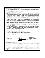
Страница 1: ...S 650 RS Installation Manual KIT CONTENTS 1 Remote Start Control Module 2 3 Button RF Keychain Transmitters 2 Wiring Harnesses 1 Parts Bag Containing 2 Fuses 2 Fuse Holders 1 Control Switch 1 Programm...

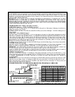
Страница 2: ...ignition key is turned to the START or CRANK position and 0 Volts when the ignition key is in any other position NOTE If installing the APS 650 RS with an alarm that utilizes a starter cut relay make...

Страница 3: ...ht switch in the vehicle switches 12 Volts do not use the Grey w Black wire see Brown w Black tracer wire BROWN Wire Positive Inhibit Input 1 Any time 12 Volts is applied to the Brown wire the Remote...

Страница 4: ...trigger wire from the shock sensor and connect one side of the cut wire to terminal 30 of the relay Connect the other side of the cut wire to terminal 87a of the relay Just before the remote starter...

Страница 5: ...Blue Wire Delayed 300 mA Pulsed Output Channel 2 The dark blue wire pulses to ground via an independent RF channel from the keychain transmitter This is a transistorized low current output and should...

Страница 6: ...ogram these selectable features 1 Start with the programming switch in the OFF position 2 Turn the ignition key to the ON position 3 Flip the program switch ON OFF ON OFF ON then OFF 4 Immediately tur...

Страница 7: ...er to distinguish the control switch from the program switch 2 Mount the control module behind the dash using cable ties or sheet metal screws 3 Securely tape and tie all wiring up and away from all h...

Страница 8: ...HIBIT1 NEGATIVEINHIBIT2 TACH SPLICE EXISTING BRAKESWITCH IGNITION3 O R SHOCKBY PASS TOCHASSIS GROUND EXISTINGPARKINGLAMPWIRE SPLICE PARKINGLAMP BROWNw BLACK BROWN BLACKw WHITE CHASSIS GROUND GREYw BLA...

Страница 9: ...L ENSEMBLE COMPREND 1 Module de t l commande distance 2 Transmetteur RF trois boutons pour porte clefs 2 Ensemble de c blage 1 Trousse d assemblage de pi ces contenant 2 Fusibles 2 Porte fusibles 1 I...

Страница 10: ...A fournis cet effet sur chacun des fils La batterie source 2 fournit 12 Vcc au module APS 650 RS pour la sortie de d marrage et la sortie pour accessoires Fil JAUNE Sortie de d marrage Connecter ce f...

Страница 11: ...t interrupteur Si l interrupteur du voyant de frein du v hicule tablit le contact avec le 12 Vcc ne pas se servir du fil GRIS R NOIRE voir Fil BRUN R NOIRE Fil BRUN Inhibition positive entr e 1 Chaque...

Страница 12: ...e la clef de contact et se procurer une r sistance de m me valeur plus ou moins 5 2 Rep rer la paire de fils VATS du v hicule Ce sont habituellement deux fils de faible calibre et reliant l interrupte...

Страница 13: ...RF ind pendant sur la t l commande C est une sortie transistoris e bas courant et elle ne doit tre utilis e que pour amorcer un relais ext rieur Cette sortie est activ e en appuyant sur la m me touche...

Страница 14: ...ment pour chaque fonction Remarque Ne pas d passer 15 secondes entre les tapes de programmation Autrement cette derni re prendra fin automatiquement 2 La programmation du tachym tre La t l commande de...

Страница 15: ...es deux commutateurs 2 Fixer le module de contr le derri re le tableau de bord en utilisant des attaches de c blage ou des vis m tal 3 S assurer que toutes les connexions soient bien isol es et que le...

Страница 16: ...EUR DU CAPOT C blage des entr es sorties 12 broches Vers 12Vcc si les feux de stationnement sont de type alimentation positive Vers la masse si les feux de stationnement sont de type alimentation n ga...

Страница 17: ...dulo de control de arranque remoto 2 Transmisores RF de llavero con 3 botones 2 Arneses de cableado 1 Bolsa con piezas que contienen lo siguiente 2 fusibles 2 portafusibles 1 interruptor de control 1...

Страница 18: ...voltios cuando la llave de contacto est en cualquier otra posici n NOTA Si se instala el APS 650 RS con una alarma que utilice un rel de corte del arrancador f jese que el cable amarillo est conectado...

Страница 19: ...uptor del veh culo conmuta 12 voltios no use el cable gris y negro v ase el cable testigo marr n y negro Cable MARR N Entrada 1 positiva de bloqueo Toda vez que se aplique 12 voltios al cable marr n e...

Страница 20: ...el par de cables VATS en el veh culo normalmente un par de cables delgados que van del interruptor de encendido a la unidad de control VAT 1 NOTA Normalmente estos cables son un cable testigo blanco y...

Страница 21: ...go azul y verde y negro Conector blanco de 2 clavijas Salidas de accesorios Cable azul oscuro Salida pulsada demorada de 300mA Canal 2 El cable azul oscuro pulsa a masa por medio de un canal de RF del...

Страница 22: ...ta Una vez que entre al modo de programaci n de funciones no deje pasar m s de 15 segundos entre un paso y el otro en caso contrario se terminar la programaci n 2 Programaci n del r gimen del taqu met...

Страница 23: ...tinguir f cilmente el interruptor de control del de programaci n 2 Monte el m dulo de control detr s del tablero con las conexiones de cables o los tornillos para metal 3 Cubra con cinta y ate todos l...

Страница 24: ...OLTIOS PARA LAS LUCES DE ESTACIONAMIENTO CON CONMUTACI N POSITIVA ALABATER ADE 12VOLTIOSPARALASLUCESDEESTACIONAMIENTOCONCONMUTACI NNEGATIVA MARR N Y NEGRO MARR N INTERRUPTOR DE FRENO EXISTENTE BLOQUEO...

Отзывы: