background image

128-7199

11 of 16

11

first programming tach, the unit will flash the parking lights 7 times indicating tach has not been learned and stored.
If the tach rate is not properly programmed to the specific vehicle, the unit may not realize that the vehicle is running
in certain instances and could re-engage the starter motor.
The Remote Car Starter will learn the tach rate of most vehicles single ignition coils, multiple coil packs, and or single
injector.  To learn tach;
1.  Turn the ignition key to the ON position.
2.  Press and release the program push-button switch 3 times.
3.  Immediately turn the ignition key OFF.
4.  Hold the program push-button switch ON, then start the vehicle 

using the ignition key

.

5.  When the unit senses the tach signal, the parking lights will begin to flash.
6.  Release the program push-button switch.  The parking lights will turn on for 3 seconds to indicate that the tach signal

is stored and the unit is now out of the program mode.

3. Diagnostics:

1.  Be sure that programmable feature number #6 is set to the "Diagnostics On" mode.
2.  Press and hold the program push-button switch on, then turn the ignition key to the "ON" position.
3.  The lights will flash and the number of flashes will indicate the reason for shutdown on the last remote start attempt.

The indications are as follows.

1 Flash

5, 10, 15, or 20, minute run timer expired.

2 Flashes

Low or No tach signal received.

3 Flashes

Positive or Negative input shut down.

4 Flashes

Control switch was moved to "Off" position.

5 Flashes

RF Shutdown command received.

6 Flashes

High RPM signal over speed shut down.

7 Flashes

Tach has NOT learned.

Multi Coil Pack Adapter: 

(Optional)

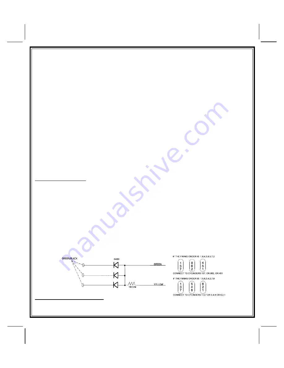
The multi coil pack adapter, (P/N 136B1400),  is designed for use with vehicles that do not respond to single coil tach
programming.  Although the tach resolution of this circuit is designed to interface direct with most vehicles, there may
be an occasion where the following circuit may be required.
To use the adapter, the Green/Black wires must connect to the negative side of the ignition coil(s).
1.  For vehicles utilizing independent coils per cylinder, connect the three Green/Black leads to alternate coils. To

achieve optimum performance the coil signals must be evenly distributed.  This is accomplished by first mapping
out the firing order of the engine in groups of as indicated below.  Draw a circle around any of the columns. The
Green/Black wires should be connected to the negative (-) terminal of the respective cylinder number which
appears in any of the circles.

2.  For vehicles utilizing 2 cylinder firing per coil pack, connect Green/Black to the tach side of each coil pack. For 8

cylinder, four coil systems, connect to any of the three coils.

3.  Connect the Yellow wire to a +12 volt ignition 1 source.  This wire will have +12 volts with the ignition in the on and

start position and have 0 volts with the ignition in the off position.

4.  Connect the Green wire to the tach input of the Audiovox remote start unit.

TESTING YOUR INSTALLATION:
W A R N I N G ! !


The following procedure must be performed after the installation of an Audiovox Remote Start

Device.  It is the responsibility of the installing technician to complete these tests.  Failure to test the unit in the
following manner may result in personal injury, property damage, or both.

Содержание APS-55TWT

Страница 1: ...ock Harness 2 30 Amp In line Fuse Holders With Fuses 1 Control Switch 1 Plug In Push Button Programming Switch 1 Ring Terminal 4 1 2 Long Screws 1 Pin Switch 1 Remote Start Warning Label 1 Literature...

Страница 2: ...be drilled Carefully check behind the chosen location to insure the drill will not penetrate any existing factory wiring or fluid lines Drill a 1 4 hole in the desired location and thread the hood pi...

Страница 3: ...feed wires must be used for the Red and Red White wires If your vehicle does not have two battery feed wires at the ignition switch then it is possible to connect both wires to the vehicle s battery...

Страница 4: ...that powers the glow plugs if the vehicle requires glow plug pre heating GREEN WIRE Ignition 2 Output Connect this wire to the ignition 2 wire from the ignition switch This wire will show 12 volts whe...

Страница 5: ...em failure to use this feature can result in serious injury Route the wire to the pin switch and connect it using the bullet connector provided GRAYw BLACKTRACERWIRE NegativeInhibitInput2 Any time the...

Страница 6: ...ng Light Flasher These wires are the COMMON and NORMALLY OPEN contacts of the on board parking lamp relay If the vehicle s parking lights are a 12 volt switched system connect 1 of the White wires to...

Страница 7: ...ystem installed you will need to bypass the system while the vehicle is operating under the control of the Remote Start Unit To Do This 1 Measure the resistance of the resistor pellet on the ignition...

Страница 8: ...S The auxiliary 4 pin connector provides low current outputs to control various functions in the vehicle during different stages of the Remote Start unit s operation Understanding these outputs and th...

Страница 9: ...es a ground pulse during the arming sequence or pulsed ground lock output Connect the Red wire to the low current ground signal wire from the factory door lock switch to the factory door lock relay Th...

Страница 10: ...or is firmly seated making good contact to the control unit 1 RF Programmable Features Feature Selection 1 Flash 2 Flash 3 Flash 4 Flash Default 1 Run Time 5 Min 10 Min 15 Min 20 Min 10 Min 2 Ign 2 Du...

Страница 11: ...igh RPM signal over speed shut down 7 Flashes Tach has NOT learned Multi Coil Pack Adapter Optional The multi coil pack adapter P N 136B1400 is designed for use with vehicles that do not respond to si...

Страница 12: ...DOWN ENABLE FEATURE NEUTRALSTART SAFETY TEST The intent of the neutral start switch is to prevent the vehicle from starting while the gear selector is in any position other than Park or Neutral When i...

Страница 13: ...he ECM in GM B Body vehicles or locate the equivalent reference wire in the vehicle you are installing the Audiovox Remote Start Unit in 2 Connect the Cathode Striped end of a 4000 series diode to thi...

Страница 14: ...ve shut down safety wire Gray Black of the Audiovox Remote Start Unit F Connect terminal 86 of the relay to a fused 12 volt constant battery source G Connect terminal 87 of the relay to the Chime Modu...

Страница 15: ...onfirmed the operation of the Audiovox Remote Start unit and tested all the safety features of the system 1 If you have not done so already place the red rubber handle cover over the handle of the con...

Страница 16: ...128 7199 16 of 16 2004 Audiovox Electronics Corp Hauppauge NY 11788 128 7199...

Отзывы: