background image

6

19

2.2 INSTALLATION OF EASERA GATEWAY DRIVERS

Windows XP

Installation Steps: 

- Quit all currently running applications

- Insert CD-ROM Driver Installation included with your EASERA GATEWAY into your com-
puter. (DO NOT CONNECT YOUR EASERA GATEWAY AT THIS TIME.)

- CD should auto run. (If not, navigate to CD and double click on Setup.exe

Carefully read and follow the EASERA GATEWAY installation instructions. The installer will
prompt you to connect your EASERA GATEWAY at the proper time. 

(NOTE: If you are connecting the EASERA GATEWAY via a standard 6-pin Firewire cable,
power for the unit will be supplied via the Firewire cable. If you are using a 4 to 6-pin
Firewire cable, you will need to connect the included external power supply to power the
EASERA GATEWAY.) This installation procedure will also install the EASERA GATEWAY
Control Panel and Mixer software.

Note: If at any point during installation a “Software Installation” message appears from
Windows regarding Windows Logo testing click “Continue Anyway” to continue installation.

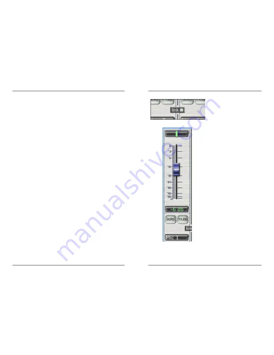
Link 

– links the input gain of adjacent

channels. If the two channels do not
have the same level when the link button
is pressed, clicking on one of the faders
will send the other input level to the
same level as the channel that was
clicked on.

Input (software playback channel) 

This is the audio return from your audio
software. The same functions are avail-
able as the other inputs including PAN
(balance between left and right chan-
nels), LEVEL, SOLO and MUTE. This is
a stereo channel. This channel picks up
the audio stream that is sent from your
software and enables you to mix it with
the direct input of your EASERA GATE-
WAY.

PLAYBACK

– Indicates the stereo

stream output channels from your soft-
ware. 

2  INSTALLATION AND SETUP

4  MIXER

Содержание EASERA

Страница 1: ...rt Analog to Digital Converters 24 bit up to 96khz ADC Dynamic Range 107db DAC 24 bit up to 96kHz DAC Dynamic Range 110db IEEE1394 Speed 400mbps As a commitment to constant improvement PreSonus Audio...

Страница 2: ...of any express or implied warranty including among other things damage to property damage based on inconvenience or on loss of use of the product and to the extent permitted by law damages for persona...

Страница 3: ...synchronization and the Blue sync light will turn on Once you have the blue sync light you can then reset the Format sample rate to your desired setting 1 Overview 1 1 Introduction 4 2 Installation a...

Страница 4: ...mic and ribbon microphones and typically require external 48V phantom power NOTE If you are using a ribbon microphone please check the manual for the mic before applying phantom power Applying phantom...

Страница 5: ...you load o 2 1 COMPUTER REQUIREMENTS Below are the minimum computer system requirements for your EASERA GATEWAY Windows OS Microsoft Windows XP Computer Windows compatible computer with FireWire port...

Страница 6: ...dure will also install the EASERA GATEWAY Control Panel and Mixer software Note If at any point during installation a Software Installation message appears from Windows regarding Windows Logo testing...

Страница 7: ...usts the input level of each input Double clicking on the blue fader automatically sets the fader to full gain Solo by pressing Solo all other input chan nels are muted Mute Mutes input channel Macint...

Страница 8: ...g function or mute the track in your software 2 Select playback channels of the main output of your audio software in the SOFTWARE PLAYBACK channel of the EASERA GATEWAY mixer The input on this channe...

Страница 9: ...INTERNAL Latency Sets the amount of delay time of your EASERA GATEWAY 1 5ms 24ms Latency is the time it takes for the computer to process audio Lower latency settings demand more CPU resources In the...

Страница 10: ...r CPU setting High Computer Processor 2GHz and higher Medium default Computer Processor 1GHz to 2GHz Low Computer Processor 800MHz to 1GHz Line Outputs 3 4 5 6 Balanced line level outputs These connec...

Страница 11: ...with the Gateway MIDI stands for Musical Instrument Digital Interface However the MIDI standard goes well beyond just instrumentation and sequencing The MIDI inputs and outputs allow con nection and...

Страница 12: ...plugged into a line input 3 or 4 rather than into an instru ment input In other words don t plug an active instrument into the combo jacks on chan nels 1 or 2 3 Input Gain Trim Control This knob prov...

Отзывы: