background image

9.23, 9.27 Treadmill

Page 34

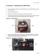
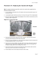
Procedure 6.5 - Replacing Drive Motor

1.

Set the treadmill’s on/off switch in the “off” position and remove the treadmill’s power cord 
from the AC outlet.

2.

Remove the hood.

3.

The drive motor and flywheel are balanced as a matched pair. Since the flywheel is 
balanced to a specific motor, flywheels should not be removed from one motor and installed 
on a different motor. If the drive motor is replaced, the drive motor and flywheel should be 
replaced as a unit.

4.

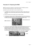
Disconnect the red and black drive motor wires from the lower PCA and green-yellow wire 
from its frame ground.

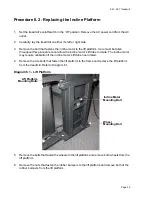
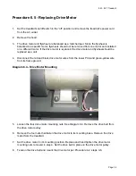
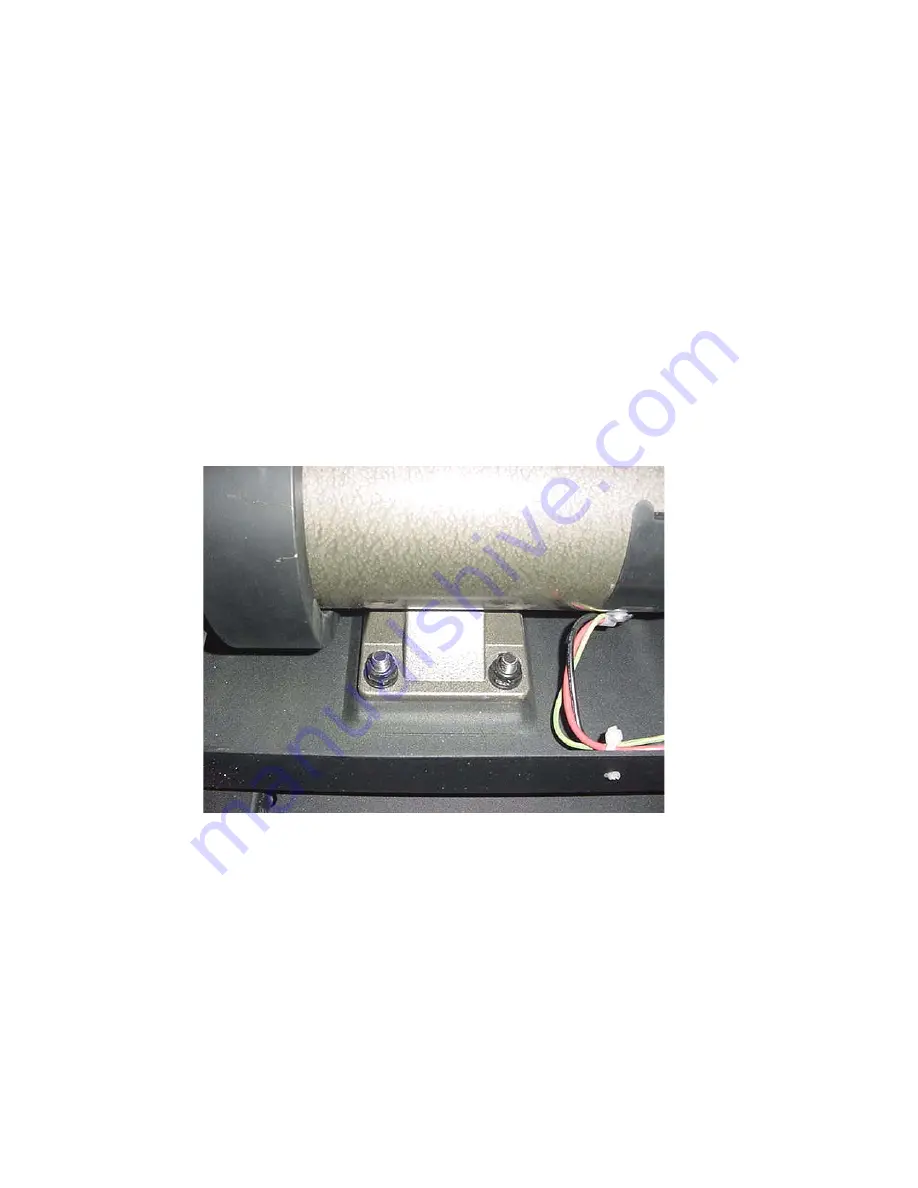
Diagram 6.4 - Drive Motor Mounting

5.

Loosen the four drive motor mounting nuts. See Diagram 6.4. Remove the drive belt from 
the drive motor pulley.

6.

Remove the four nuts that fasten the drive motor to its mounting base. Remove the drive 
motor from the treadmill.

7.

Set the drive motor in it’s mounting position. Replace and hand tighten the drive motor 
mounting nuts removed in step 4. Set the drive belt in place on the drive motor pulley.

8.

Tension the drive belt and mount the drive motor per Procedure 4.2, steps 3-6.

Содержание 9.21

Страница 1: ...n this product This document contains general product information software diagnostic procedures when available preventative maintenance procedures inspection and adjustment procedures troubleshooting...

Страница 2: ...cedures Perform inspection procedures when a trouble symptom points to a particular problem and after removing and replacing major components Many maintenance problems can be fixed by adjusting variou...

Страница 3: ...3 cm Width 30 5 inches 77 5 cm Height 55 inches 140 cm Running surface 20 inches by 59 inches 51 cm by 149 9 cm Motor 2 75 hp continuous duty DC Speed 0 5 to 12 mph 0 8 to 19 3 kph 10 mph is equivale...

Страница 4: ...2 error occurs all drive motor and lift motor motion is halted and the display is blanked except for the error display E4 This error is displayed in the display s TIME window indicating an incomplete...

Страница 5: ...rrent exceeds 28 amps the current limit circuit is activated When current limit is activated the drive motor current and speed can not be increased MOT DRV Indicates a defective drive motor circuit Ty...

Страница 6: ...s the ENTER key to toggle the display to the hour meter 3 HOUR will appear in the main window and the treadmill s hours of use will be displayed in the time window in the format XXXXX XX Pressing the...

Страница 7: ...the INCLINE S and SPEED T keys until the display goes blank The word init will appear in the display s time window The EEPROM has now been cleared and reset After 1 1 4 seconds 1 25 will be displayed...

Страница 8: ...version 2 2 and greater contain the option of selecting U S Standard or metric measurements 1 Within 2 seconds of power up press the STOP INCLINE S and SPEED T keys sequentially 2 Press one of the arr...

Страница 9: ...ormation Model and serial number Provide the model number as accessed in Procedure 2 2 Program number running when the problem occurred A description of a What happened or failed to happen b The actio...

Страница 10: ...sage PRESS QUICKSTART OR PROGRAM 3 Place the treadmill in Manual Mode Adjust the speed of the running belt to 2 3 m p h Operate the treadmill for at least 5 minutes a Concentrate on the feel of the ru...

Страница 11: ...o the 0 incline position unless it is already in the 0 incline position 4 Press the QUICKSTART key when the running belt starts the incline will move to its 0 incline position unless it is already in...

Страница 12: ...pright position Set the on off switch in the on position Place the treadmill in the manual program and operate the incline several times between its minimum and maximum incline positions to ensure tha...

Страница 13: ...pounds 5 If the drive belt tension is less than 70 or greater than 90 pounds slightly loosen the four drive motor mounting nuts The drive motor mounts on slotted holes allowing the drive motor to be m...

Страница 14: ...23 9 27 Treadmill Page 14 Diagram 4 3 Drive Motor Mounting 6 Plug the AC power cord into the AC outlet and set the treadmill circuit breaker in the on position 7 Check treadmill operation per Section...

Страница 15: ...witch in the off position and remove the AC power cord from the AC outlet 3 Remove the four screws that fastens the backplate to the rear of the console and remove the backplate Refer to Diagram 6 9 T...

Страница 16: ...ect replace the console per Procedure 6 10 6 If all of the above measurements are good but a keypad key is still not functioning replace the upper PCA per Procedure 6 11 7 If you have performed all of...

Страница 17: ...ing the value of the internal potentiometer The lift motor is initially set at a known starting position calibration See Procedure 4 1 subsequent motor movement is tracked via the potentiometer resist...

Страница 18: ...gnificantly high replace the incline motor per Procedure 6 1 8 Connect an AC voltmeter between terminal 2 white wire and terminal 3 black wire of the JK4 connector on the lower PCA Press the INCLINE T...

Страница 19: ...onnections on the incline potentiometer to ensure they are securely connected to the incline potentiometer Refer to Diagram 5 3 Diagram 5 3 Incline Potentiometer 16 Repeat the three ohmmeter measureme...

Страница 20: ...d Sensor 2 Remove the treadmill s hood 3 Remove the JK2 connector from the lower PCA Refer to Diagram 5 2 4 With an ohmmeter measure between the two pins on the JK2 connector and slowly push the runni...

Страница 21: ...itch per Procedure 6 7 5 Ensure that the safety key magnet is operating the reed switch in the console If the reed switch is not activated the display will not illuminate See Procedure 5 5 6 Remove th...

Страница 22: ...9 23 9 27 Treadmill Page 22 Diagram 5 5 Circuit Breaker and On Off Switch Circuit Breaker Reset Button On Off Switch AC Power Cord...

Страница 23: ...iagram 5 6 JK1 Connector Lower PCA 14 With a DC voltmeter measure between VCC orange wire and GND green wire on the JK1 connector on the lower PCA The reading should be approximately 16 Vdc If the rea...

Страница 24: ...rom the upper PCA 3 With an ohmmeter measure between the two pins of the JK5 connector with the safety key installed on the console in its operating position and with the safety key removed from the c...

Страница 25: ...et the on off switch in the on position 4 Set the treadmill to operate in the manual program at 1 mph 5 With a DC voltmeter measure between the T3 M terminal and the T4 M terminal on the lower PCA The...

Страница 26: ...Procedure 6 11 13 If the display does not indicate that the speed should be increasing when the SPEED S key is pressed bypass the interconnect cable with a known good interconnect cable It is not nece...

Страница 27: ...t breaker with a capacity of less than 15 amps the A C circuit must be corrected to be a 15 amp dedicated circuit before any reliable troubleshooting can be performed on the treadmill More importantly...

Страница 28: ...ircuit breaker If the circuit breaker is greater than 15 amps the circuit breaker should be replaced with a 15 amp circuit breaker If the circuit breaker is less than 15 amps the circuit breaker must...

Страница 29: ...cline motor to its upper mounting bracket 7 Remove the incline motor from the treadmill 8 Set the replacement incline motor at its mounting position and fasten it to its upper mounting bracket with th...

Страница 30: ...lift tube to rotate The incline motor may require calibration if the incline motor s lift tube has rotated 4 Remove the two bolts that fasten the lift platform to the frame and remove the lift platfor...

Страница 31: ...are removed in step 5 9 Set the replacement lift platform in its mounting position and fasten it with the hardware removed in step 4 10 Fasten the incline motor s lift tube to the lift platform with t...

Страница 32: ...two screws that fasten the lower PCA to the frame and remove the lower PCA from the treadmill 6 Set the replacement lower PCA at its mounting position and fasten it with the hardware removed in step 4...

Страница 33: ...and remove the speed sensor from the treadmill Diagram 6 3 Speed Sensor 5 Set the replacement speed sensor at its mounting position and fasten it with the hardware removed in step 4 6 Dress the speed...

Страница 34: ...hould be replaced as a unit 4 Disconnect the red and black drive motor wires from the lower PCA and green yellow wire from its frame ground Diagram 6 4 Drive Motor Mounting 5 Loosen the four drive mot...

Страница 35: ...e T4 M terminal of the lower PCA the red wire removed in step 3 to the T3 M terminal of the lower PCA and the green yellow lead to its frame ground termination 10 Dress the drive motor wires and faste...

Страница 36: ...emove the circuit breaker from the mounting plate refer to Diagram 6 5 Diagram 6 5 Circuit Breaker 4 Press the replacement circuit breaker into its mounting hole until it snaps into place 5 Connect th...

Страница 37: ...ress the four clips on the on off switch two on the top and two on the bottom and push the on off switch out of the front of its mounting plate Refer to Diagram 6 6 Diagram 6 6 On Off Switch 5 Orient...

Страница 38: ...wire from the AC power cord to the lower right hand terminal of the on off switch the red wire from the circuit breaker to the upper left hand terminal of the on off switch and the red black wire from...

Страница 39: ...ng to disengage from the brush holder and slide out of the brush holder 5 Disconnect the brush connector and remove the brush from the brush holder 6 Slide the replacement brush into the brush holder...

Страница 40: ...hey are a 28 pin dual in line package DIP28 and a forty four pin square package PLCC44 Each of these packages should be removed with a proper IC removal tool see the illustrations below 4 The IC s may...

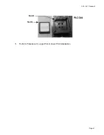
Страница 41: ...9 23 9 27 Treadmill Page 41 5 Perform Procedure 2 3 upper PCA to lower PCA initialization Notch Notch PLCC44...

Страница 42: ...View 4 Disconnect the interconnect cable from the JK1 connector on the lower PCA Cut and remove the cable ties that retain the interconnect cable 5 Remove four screws that fasten the console to the ta...

Страница 43: ...connector on the upper PCA 12 Snap the safety switch removed in step 6 into its mounting on the console Connect the safety switch connector to the SW1 connector on the upper PCA 13 Set the safety swit...

Страница 44: ...nect the keypad connector from the JK5 connector on the upper PCA 6 When furnished disconnect the heart rate connector from the JK2 connector on the upper PCA 7 Remove the five screws that fasten the...

Страница 45: ...f the upper end of the targa upright Stop when the string is projecting out of the upper and lower ends of the targa upright Remove the interconnect cable from the string and discard the interconnect...

Страница 46: ...te to the console and remove the backplate Refer to Diagram 6 9 4 Disconnect the safety switch connector SW1 from the upper PCA Unsnap the safety switch from its mounting in the console 5 Snap the rep...

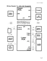
Страница 47: ...9 23 9 27 Treadmill Page 47 Wiring Diagram 7 1 9 23 9 27 Treadmills...

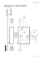
Страница 48: ...9 23 9 27 Treadmill Page 48 Block Diagram 7 2 9 23 9 27 Treadmills...

Отзывы: