Precor 9.10 Скачать руководство пользователя страница 7

905E, 9.1, 9.10 Treadmills

Page 7

Procedure 2.3 - Selecting United States Standard or Metric 

Units

Selecting United States standard units causes information to be displayed in feet and pounds. 
Information is displayed in meters and kilograms if metric units are selected. After you have 
selected a measurement standard, the software compiles and records workout information in the 
units of the measurement standard selected. Changing to the alternate measurement standard 
after your workout has started will cause invalid data to be displayed. For this reason, change the 
measurement standard only after turning ON the treadmill.

Procedure

The measurement standard must be changed within five seconds of turning on the treadmill.

1.

Place the magnetic safety key in the 

ACTIVATE

 position, then turn on the treadmill with the 

circuit breaker.

2.

With the Enter Your Weight banner scrolling, press and hold the 

SPEED


 and 

SCAN/

ENTER

 keys simultaneously until the 

Press 

 for MPH & miles or 

 for KPH & 

kilometer

s message scrolls across the screen.

3.

Use the 

SPEED


 or 

SPEED


 key to select the measurement standard.

Note:

When the treadmill is turned off or unplugged it will remember the last measurement standard 
selected. 

Содержание 9.10

Страница 1: ...ntain this product This document contains general product information software diagnostic procedures when available preventative maintenance procedures inspection and adjustment procedures troubleshoo...

Страница 2: ...can be fixed by adjusting various treadmill components This section also provides you with the step by step procedures required to make these adjustments Section Five Troubleshooting Procedures The di...

Страница 3: ...p continuous duty DC Speed 905e Treadmills Software Version 1 4 or Less 0 3 to 6 mph in 2 mph increments 905e Treadmills Software Version Greater Than 1 4 0 5 to 8 mph in 2 mph increments 9 1 Treadmil...

Страница 4: ...9 1 2 The 9 10 Treadmill electronic console is shown in Diagram 9 1 3 2 With the Enter Your Weight banner scrolling press and hold the SPEED key SPEED key STOP and SCAN ENTER keys simultaneously 3 Th...

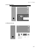
Страница 5: ...905E 9 1 9 10 Treadmills Page 5 9 1 Electronic Console 9 10 Electronic Console...

Страница 6: ...vided with the 905e 9 1 and 9 10 Treadmills Procedure 1 Place the magnetic safety key in the ACTIVATE position then turn on the treadmill with the circuit breaker 2 With the Enter Your Weight banner s...

Страница 7: ...will cause invalid data to be displayed For this reason change the measurement standard only after turning ON the treadmill Procedure The measurement standard must be changed within five seconds of tu...

Страница 8: ...he ACTIVATE position then turn on the treadmill with the circuit breaker 2 With the Enter Your Weight banner scrolling press and hold the SPEED key SPEED key STOP and SCAN ENTER keys simultaneously 3...

Страница 9: ...ED key SPEED key STOP and SCAN ENTER keys simultaneously 3 After the software version number is displayed on the electronic console watch the illuminated lines sweep from top to bottom and then right...

Страница 10: ...ess and hold the SPEED key SPEED key STOP and SCAN ENTER keys simultaneously 3 Watch the electronic console When the potentiometer increment number is displayed on the electronic console enter power b...

Страница 11: ...hen a problem occurs record the following information Model and serial number Software version number Note Determine the version number of the PROM mounted on the upper PCA as described in Procedure 2...

Страница 12: ...ed and unloaded conditions Press the SCAN key while observing the LED s on the electronic console Make sure that each LED lights as the information corresponding to that LED is displayed on the electr...

Страница 13: ...he crank handle will no longer move without using excessive force 6 Press the SCAN key then view the electronic console as the treadmill scans time speed distance and percent 7 If the electronic conso...

Страница 14: ...sion number recorded in Step 9 is equal to or greater than 4 0 THEN OTHERWISE Rotate the pin wheel until the Rotate the pin wheel until the electronic console displays 18 electronic console displays 1...

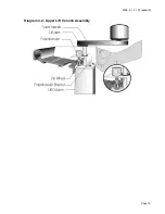
Страница 15: ...905E 9 1 9 10 Treadmills Page 15 Diagram 4 2 Upper Lift Column Assembly...

Страница 16: ...ground lead of the wrist strap to the treadmill frame 4 Set the voltmeter to a range that will conveniently read 6 Vdc 5 Set the circuit breaker in the on position 6 Use a DVM set for DC volts and re...

Страница 17: ...ect replace the upper PCA 9 If the voltage readings in Table 5 1 are correct and one or more voltage readings in Table 5 2 are incorrect replace the display housing keypad 10 Set the circuit breaker i...

Страница 18: ...cuit breaker with a capacity of less than 20 amps the A C circuit must be corrected to be a 20 amp dedicated circuit before any reliable troubleshooting can be performed on the treadmill More importan...

Страница 19: ...mp circuit breaker If the circuit breaker is greater than 20 amps the circuit breaker should be replaced with a 20 amp circuit breaker If the circuit breaker is less than 20 amps the circuit breaker m...

Страница 20: ...unplug the treadmill from the wall outlet WARNING Before continuing with this procedure review the Warning and Caution statements listed in Section One of the Residential Treadmill Service Manual 2 R...

Страница 21: ...2 of this appendix 7 Remove the screws that secure the electronic chassis to the electronics housing assembly Note The electronics housing assembly is the frame that holds together the electronic cons...

Страница 22: ...dure 2 7 of this appendix Diagram 6 3 Removing the Electronic Console Replacing the Upper PCA 12 Position the new upper PCA at its mounting location Install the screws that secure the PCA to the elect...

Страница 23: ...d 20 Remove the adhesive cover from the back of the new keypad then carefully position the keypad on the electronics housing assembly Press the keypad firmly 21 Remove the adhesive cover from the back...

Страница 24: ...ers that secure the electronic console to the upper handrail clamp 4 Remove the screws that secure the upper electronic chassis to the electronics housing assembly 5 Attach the wrist strap to your arm...

Страница 25: ...rest on the right handrail Diagram 6 4 Partial Layout of the Upper PCA 13 Remove the ground lead of the wrist strap from the treadmill frame then remove the wrist strap from your arm 14 Check the ope...

Страница 26: ...the electronics housing assembly 19 Position the electronic console at its mounting position 20 Replace the bolts and washers that secure the electronic console to the upper handrail clamp 21 Positio...

Страница 27: ...lift potentiometer from the potentiometer mounting bracket as described in Procedure 6 7 of this appendix 4 Position the crank handle on the lift jack shaft and tighten the screw 5 Rotate the crank ha...

Страница 28: ...ibbon cable into the top of the lift column until only 6 8 inches of cable are hanging out of the top of the lift column Fold the top of the ribbon cable over the top edge of the lift column and use t...

Страница 29: ...her and then a new pressure washer on the collar 24 Position an empty tube or pipe on the pressure washer and use the hammer to force the pressure washer spacer washer and collar further down on the l...

Страница 30: ...ills Page 30 Diagram 6 6 Exploded view of Lift Assembly 32 Calibrate the lift assembly as described in Procedure 4 1 of this appendix 33 Check the operation of the treadmill as described in Section Th...

Страница 31: ...n statements listed in Section One of the Residential Treadmill Service Manual 4 Lift the hood as described in Procedure 5 1 of the Residential Treadmill Service Manual 5 Disconnect the ribbon cable f...

Страница 32: ...electronic console on the upper handrail clamp Replace the bolts and washers that secure the electronic console to the upper handrail clamp 16 Position the crank handle at its mounting position and u...

Страница 33: ...ntain the vertical alignment of the trim with the lift column CAUTION Make sure that the ribbon cable is situated in the trim s center slot before you perform the following step d While maintaining al...

Страница 34: ...al Treadmill Service Manual 5 Attach the anti static wrist strap to your arm then connect the ground lead of the wrist strap to the treadmill frame 6 Disconnect the ribbon cable from the lower PCA 7 D...

Страница 35: ...tor chassis 14 Attach the ribbon cable to the lower PCA 15 Connect the wires listed in Table 9 1 3 to the lower PCA 16 Remove the ground lead of the wrist strap from the treadmill frame then remove th...

Страница 36: ...potentiometer shaft If necessary deflect the potentiometer bracket to allow the pin wheel to clear the end of the potentiometer shaft Set aside the pin wheel 4 Remove the jam nut and star washer secur...

Страница 37: ...9 10 Treadmills Page 37 Note Place a drop cloth under the treadmill to protect the flooring and to ensure that the treadmill handrail is not scratched or damaged Diagram 6 8 Exploded View of the Lift...

Страница 38: ...ing the appropriate procedure listed in Table 6 2 Table 6 2 Replacing the Ribbon Cable Procedures Procedure 6 3 905e Treadmills and 9 1 Treadmills Made Before September 14 1994 Procedure 6 4 9 10 Trea...

Страница 39: ...k shaft so that the base of the collar is at the lower end of the shaft 25 Place the spacer washer and then a new pressure washer on the collar 26 Position an empty tube or pipe on the pressure washer...

Страница 40: ...wheel from the potentiometer shaft If necessary deflect the potentiometer bracket to allow the pin wheel to clear the end of the potentiometer shaft Set aside the pin wheel 7 Remove the jam nut and s...

Страница 41: ...ing over the soldered connection 14 Using a new cable tie secure the three potentiometer wires to the potentiometer bracket 15 Calibrate the lift assembly as described in Procedure 4 1 of this appendi...

Страница 42: ...andrail clamp as well as the handrails THEN OTHERWISE Continue with next step Skip to Step 10 Removing the Upper Handrail Assembly 6 Remove the electronic console as described in Procedure 6 1 of this...

Страница 43: ...ame 12 Position the right lower handrail clamp at its mounting location Replace the screws that secure the clamp to the treadmill frame 13 Repeat Steps 11 through 13 for the left handrail clamp 14 Tig...

Страница 44: ...905E 9 1 9 10 Treadmills Page 44 Diagram 7 1 Wiring Diagram 905e 9 1 9 10...

Страница 45: ...905E 9 1 9 10 Treadmills Page 45 Diagram 7 2 Block Diagram 905e 9 1 9 10 Treadmills...

Отзывы: