


flat on the housing journal.
(1)Preparing for Drilling(see fig.2)(Except addition power feed system).
Turn of the knob make loose the taper body of worm gear and spring
base. Then we decide spindle stroke setting the positive depth stop
gauge for drilling blind hole or free state for pass hole.
(2)Preparing for Milling (see fig.2)(Except addition power feed system).
(a)Adjust the positive depth stop gauge to highest point position.
(b)Turn tight of the knob be use to taper friction force coupling the worm
gear and spring base. Then turning the handle wheel by micro set the
spindle of work piece machining height.
(c)Lock the rack sleeve at the desired height with fixed bolt.
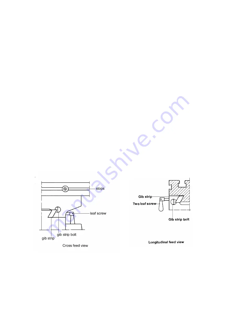
ADJUSTING TABLE SLACK AND COMPENSATE FOR WEAR(see fig.3)
(1)
Your machine is equipped with jib strip adjustment to compensate for
wear and excess slack on cross and longitudinal travel.
(2)
Clockwise rotation the job strip bolt with a big screw for excess slack
otherwise a little counter clockwise if too tight.
(3)
Adjust the jib strip bolt until feel a slight drag when shifting the table.
CLAMPING TABLE BASE AND MACHINE BASE(See Fig.3)
(1)
When milling longitudinal feed. It is advisable to lock the cross feed table
travel to insure the accuracy of your work. To do this, tighten the
Fig.3
small leaf screw located on the right side of the table base.
(2)
To tighten the longitudinal feed travel of the table for cross feed milling,
tighten the two small leaf screw on the front of the table base.
(3)
Adjustable travel stops are provided on the front of the table for control of
cross travel and the desired milling length.
Содержание PM-940V-PDF
Страница 9: ......
Страница 11: ......
Страница 13: ......
Страница 16: ...BASE ...
Страница 19: ...Certificate of Inspection for Milling and Drilling Machine Model PM 940V PDF Dispatch No ...
Страница 20: ...The machine has been qualified and may be permitted to dispatch Head of inspection depart Date Director Date ...


