5
Copyright © 2020 Quality Machine Tools, LLC
PM-835S v3 2020-10
Section 2 INSTALLATION
Cleanup
Finished metal surfaces such as the ways and table are pro-
tected in shipping by grease and/or paper. After uncrating the
mill, clean the finished surfaces using a plastic paint scraper,
disposable rags, and a light oil such as WD-40.
Reverse the hand cranks, if they were installed inside out for
shipping (or they may have been shipped loose).
Preliminary oiling
Before cranking the table, knee, saddle and ram into position
for hoisting, apply oil to the ways using the one-shot oiler — a
couple of pump strokes should be sufficient. Crank the table,
knee and saddle through at least one end-stop to end-stop
cycle. If the lube reservoir is empty, replenish with Mobil Vactra
No. 2 or equivalent (see Section 4, Maintenance).
Moving the head
If it is necessary to swivel the head for hoisting purposes, par-
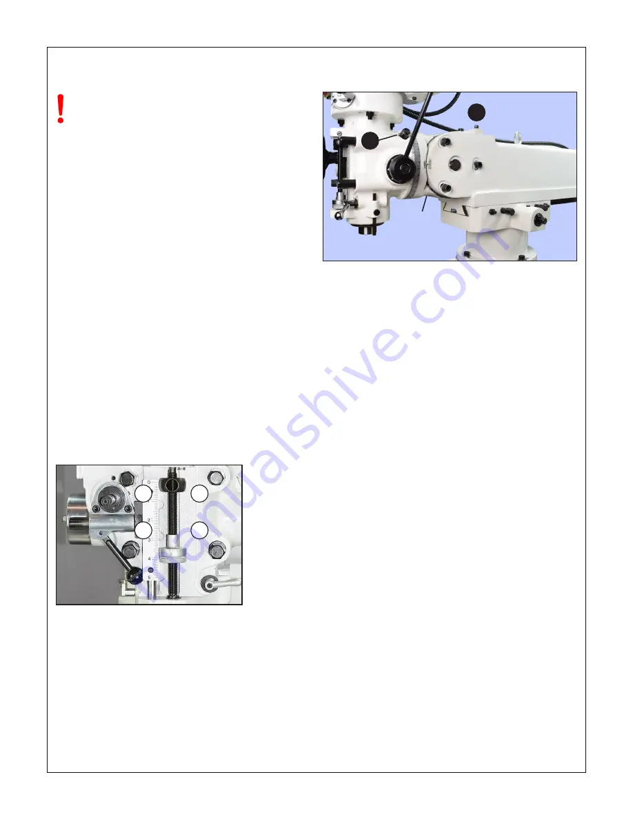
tially loosen the four head mounting bolts, Figure 2-1,
while
supporting the head
to prevent sudden movement. Continue
supporting the head while using a wrench on hex head #1,
Figure 2-2, to crank the head to the desired position. Tighten
the bolts in the diagonal sequence, Figure 2-1, first pass at 25
lb-ft torque, second pass at 50 lb-ft. Over-tightening can distort
the head, causing the quill to bind.
Do not move the table, saddle, knee — or any
other movable part — until everything has been
thoroughly cleaned and lubricated, see below
Figure 2-2
Head swivel & head forward/backward tilt
Use a hex wrench to crank the head clockwise/counter-clockwise (1)
—
support the head manually while turning to ease pressure on
the worm
. Socket head cap screw (2) bears on a ledge on the head
support casting, allowing a few degrees angular adjustment forward
and back.
Site preparation
The floor must be capabl
e of rigidly supporting a weight of at
least 1 ton. If possible, secure the mill to the floor with anchor
bolts. Alternatively, use pads and leveling screws installed in
holes in the machine base (pads are available from Precision
Matthews).
If the machine is to be bolted down, be sure that all four cor-
ners of the base are
solidly
in contact with the floor
after the
machine has been leveled
, see below. Use metal shims to
correct if necessary.
Lifting the mill
See Figures 2-3 and 2-4 for alternatives. Go slow! Check for
balance as the mill is clearing the pallet or floor. It may be nec
-
essary move the head for clearance, and/or to adjust the knee,
table and ram for balance.
Leveling
Check for clearance
around the mill before settling on its final
location. Using a precision machinist’s level check the table
lengthwise (X) and crosswise (Y), shimming as necessary un-
der the base, or adjusting the leveling screws.
Figure 2-1
Head mounting bolts
The numbers indicate the correct (diagonal) tightening sequence.
2
3
1
4
Head
support
casting
1
2


