


12
PM-30MV v3 2020-10
Copyright © 2020 Quality Machine Tools, LLC
TAPPING OPERATIONS
When threading a drilled hole it is essential to align the thread-
ing tap properly in the bore. The mill is often used for this
purpose, ideally with a dedicated (non-slip) tap holder or, for
production work, an auto-reverse tapping attachment. A drill
chuck can be used instead for sizes up to (say) M6 or 1/4”,
beyond which the chuck may not grip tightly enough to avoid
slippage. Tapping can be done under power, or by hand turn-
ing the chuck.
For either method, it is essential to use a tapping fluid. Any cut
-
ting oil is better than none, but most users find Castrol’s Moly
Dee the most reliable for threading in steel.
If power tapping bear in mind that the spindle does not stop
instantaneously, so be careful tapping blind holes. Be sure the
quill locking lever is free, and start trial work with the lowest
spindle speed.
TILTING THE HEADSTOCK
In routine operations the user relies on squareness of the spin-
dle relative to both axes of the table. Front-to-back squareness
is set at the factory, and is not adjustable by everyday meth-
ods. In the other plane the headstock can be set to any angle
up to 90 degrees either side of the normal vertical position.
Because re-establishing true vertical (tramming) on any mill is
a time consuming process, most machinists look first for other
ways of handling a project instead of tilting the head.
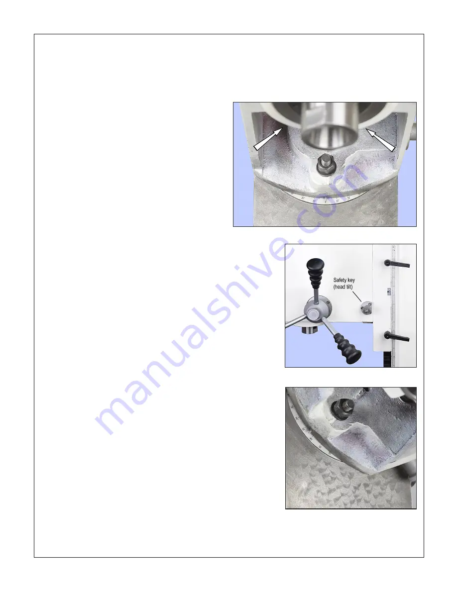
The headstock is secured by three nuts spaced 120 degrees
apart, one underneath and one each side, Figure 3-12. A
spring-loaded safety key, Figure 3-12, locks the headstock in
approximate
vertical and ± 90 degree positions; it must be
pulled out for the headstock to be rotated. The headstock is
top-heavy, and may swing suddenly to either side unless a
helper is on hand to restrain it. Testing for moveability as you
go, carefully loosen the nuts by degrees. Be especially careful
if the head has not been moved before – the paint seal may let
go without warning. (First-time tilting may also call for unusual
effort on the wrench.)
Set the headstock to the desired angle by reference to the
tilt scale on the headstock base casting, Figure 3-13, then
re-tighten the nuts. The tilt scale is typically good to within ±
1/2
o
. A more accurate means of angle measurement will be
needed if the project calls for greater precision.
3. If the reference edge is already to the back the spindle
centerline, do nothing; if not, rotate the Y-axis handwheel
clockwise to send the workpiece backwards (toward the
column), placing the reference edge behind the edge find
-
er.
4.
Engage the fine downfeed, Figure 3-10.
5. With the spindle running, lower the quill as necessary
using the fine downfeed control, then bring the table for
-
ward (counter-clockwise), stopping at the point where the
edge-finder just makes contact (the tip jumps out of line).
Stop the spindle.
6. While holding the Y-axis handwheel to prevent rotation,
zero the Y dial
. Check the zero setting by turning the
handwheel clockwise a full turn, then counter-clockwise to
touch the edge finder for the second time.
7. Raise the quill, then rotate the handwheel one exact full
turn counter-clockwise (0.1”) to bring the reference edge
to the spindle centerline. (Why? Because 0.1” is half the
assumed diameter of the edge finder.)
8. Rotate the handwheel 2-1/2 turns counter-clockwise to
bring 50 on the dial opposite the datum; the spindle is
now 0.25” to the back of the reference edge, ready for
hole drilling.
Figure 3-12
Headstock nuts
Figure 3-13
Safety key
Figure 3-14
Tilt scale: 45 degrees clockwise rotation